


21
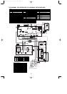
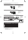
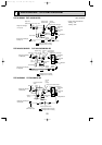
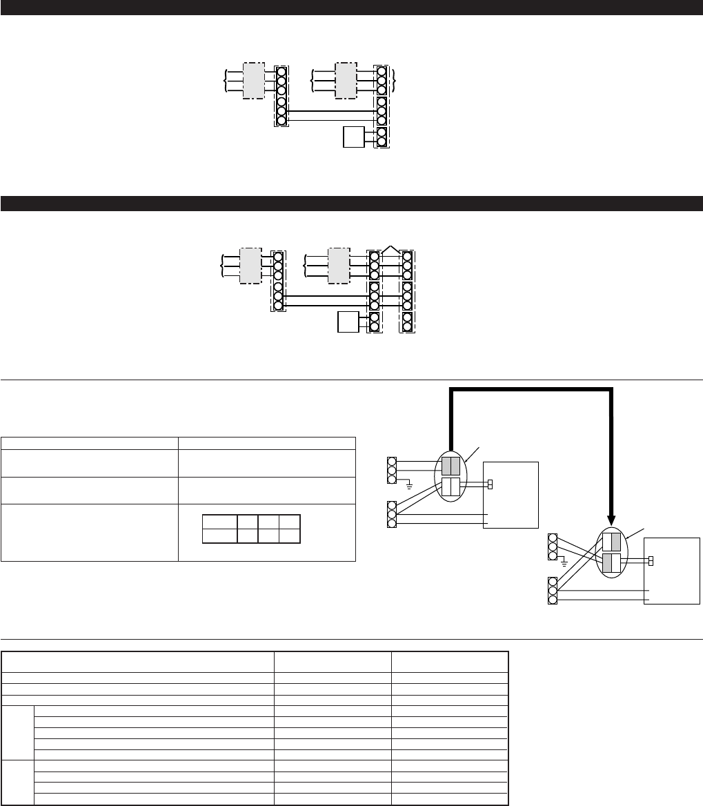
8-2. SEPARATE INDOOR UNIT/OUTDOOR UNIT POWER SUPPLIES
The following connection patterns are available.
The outdoor unit power supply patterns vary on models.
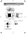
1:1 System
S1
S2
L1
L2
GR
GR
1
2
L1
L2
S1
S2
S3
S3
* Affix a label B that is included with the manuals near each wiring diagram for the indoor and outdoor units.
* The optional indoor power supply terminal kit is required.
Outdoor unit power supply
Wiring circuit breaker or isolating switch
Outdoor unit
Indoor unit/outdoor unit connecting cords
Remote controller
Indoor unit
Indoor unit power supply
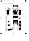
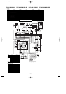
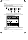
Simultaneous twin system
If the indoor and outdoor units have separate power supplies, refer to the table below.
Change the indoor unit electrical box wiring refering to the figure in the right and
the DIP switch settings of the outdoor unit control board.
*Affix a label B that is included with the manuals near each wiring diagram for the indoor and outdoor units.
Outdoor unit power supply
Wiring circuit breaker or isolating switch
Outdoor unit
Indoor unit/outdoor unit connecting cords
Remote controller
Indoor unit
Indoor unit power supply
ON
OFF 1 2
(SW8)
3
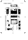
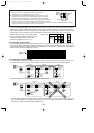
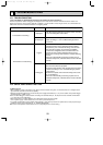
Indoor unit electrical box connector con-
nection change
Label affixed near each wiring diagram
for the indoor and outdoor units
Outdoor unit DIP switch settings (when
using separate indoor unit/outdoor unit
power supplies only)
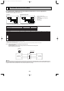
Indoor unit specifications
Required
Required
*1. Max. 50 m, 165 ft
*2. The 10 m, 30 ft wire is attached in the remote controller accessory. Max. 500 m, 1500 ft
*3. The figures are NOT always against the ground.
Notes: 1. Wiring size must comply with the applicable local and national code.
2. Use copper supply wires.
3. Use wires rated 300V or more for the power supply cables.
4. Install an earth longer than other cables.
Indoor unit model
Indoor unit power supply
Minimum circuit ampacity
Maximum rating of overcurrent protective device
Indoor unit power supply
Indoor unit power supply earth
Indoor unit-Outdoor unit *1
Indoor unit earth
Remote controller-Indoor unit *2
Indoor unit L1-L2 *3
Indoor unit-Outdoor unit S1-S2 *3
Indoor unit-Outdoor unit S2-S3 *3
Remote controller-Indoor unit *3
PLA-A12, 18, 24, 30
PKA, PCA
PLA-A36, 42
Single 208/230 V, 60 Hz Single 208/230 V, 60 Hz
1 A 2A
15A 15A
2
o Min. AWG16 2
o Min. AWG16
1
o Min. AWG16 1
o Min. AWG16
2
o AWG22 (polar) 2
o AWG22 (polar)
2
o AWG22 (Non-polar) 2
o AWG22 (Non-polar)
AC 208/230 V AC 208/230 V
DC24 V DC24 V
DC12 V DC12 V
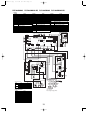
Circuit
rating
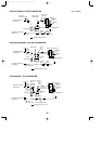
If the indoor and
outdoor units have
separate power
supplies, change the
connections of the
connectors as shown
in the following
figure.
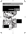
Connectors
Indoor unit
control board
Separate indoor unit/outdoor unit power
supplies
Indoor unit
control board
* There are three types of labels (labels A, B, and C). Affix the appropriate labels to
the units according to the wiring method.
S1
S2
L1
GR
L2
1
2
L1
L2
GR GR
S1
S2
S3
1
2
L1
L2
S1
S2
S3
S3
S1
S2
S3
L1
L2
GR
BLUE
BLUE
YELLOW
YELLOW
CND/CN01
S1
S2
S3
L1
L2
GR
YELLOW
BLUE
BLUE
YELLOW
Wiring
Wire No.
o
size
––
––
A
B
C
D
E
F
G
Option
H
Option
H
A
B
C
D
E
F
G
A
H
H
C
BB
D
E
F
G
A
C
BB
D
E
FF
G
CND/CN01
Connectors (connections when
shipped from the factory are
for indoor unit power supplied
from outdoor unit)
Indoor unit power supplied
from outdoor unit(When
shipped from factory)
OCH429--1.qxp 07.11.20 9:17 AM Page 21