


106
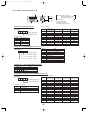
14 DISASSEMBLY PROCEDURE
OPERATING PROCEDURE
PHOTOS
PUZ-A18NHA2 PUZ-A18NHA2-BS
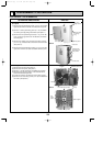
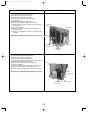
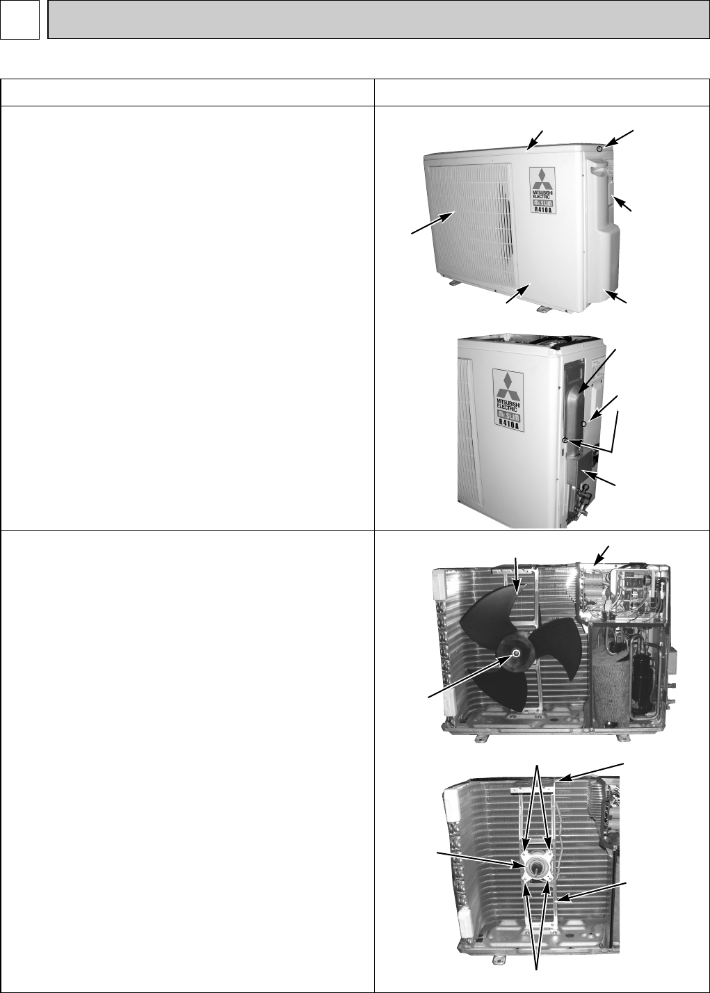
1. Removing the top panel, service panel, front panel and
back panel
(1) Remove the top panel fixing screws (4 ✕ 10), one from the
right and two from the left side, and detach the top panel.
(2) Remove 1 service panel fixing screw (4 ✕ 10) and detach
the service panel by pulling it downward. (See photo 1.)
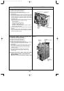
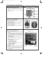
(3) Remove the front panel fixing screws (4 ✕ 10), 5 from the
front, 2 from the right and 2 from the left side, and detach
the front panel.
(4) Remove the conduit cover and cord cover fixing screw (2
pcs. 4 ✕ 10), and detach the conduit cover and cord cover.
(See photo 2.)
(5) Remove the back panel fixing screws (4 ✕ 10), 4 from the
right and 3 from the rear side, and detach the back panel.
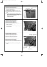
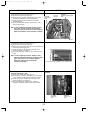
2. Removing the fan motor
(1) Remove the top panel. (See photo 1.)
(2) Remove the front panel. (See photo 1.)
(3) Remove 1 nut (M6, left-screw) and detach the propeller.
(4) Disconnect the connector CNF1 on the controller circuit
board in the electrical parts box.
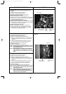
(5) Loosen the clamp for the lead wire in the motor support.
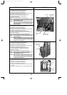
(6) Remove 4 fan motor fixing screws (4 ✕ 18) and detach the
fan motor. (See photo 3.)
Photo 1
Photo 2
Top panel
Top panel
fixing screws
Service panel
Service panel
for charge
plug
Grille
Front panel
Photo 3
Propeller
Nut
Electrical parts box
Photo 4
Fan
motor
(MF1)
Fan motor fixing screws
Fan motor fixing screws
Motor support
Clamp
Conduit cover
and cord cover
fixing screws
Cord cover
Conduit cover
OCH429--4.qxp 07.11.20 9:20 AM Page 106