


16
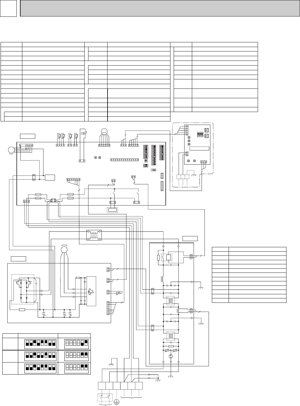
TB1
MC
MF1
21S4
63H
TH3
TH4
TH6
TH7
TH8
LEV-A
CY1,CY2
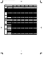
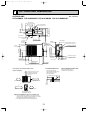
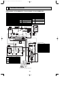
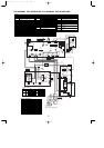
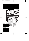
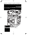
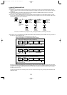
Terminal Block<Power Supply, Indoor/Outdoor>
Motor for Compressor
Fan Motor
Solenoid Valve (Four-Way Valve)
High Pressure Switch
Thermistor<Outdoor Pipe>
Thermistor<Discharge>
Thermistor<Outdoor 2-Phase Pipe>
Thermistor<Outdoor>
Thermistor<Heatsink>
Electronic Expansion Valve
Capacitor
ACL
Reactor
Power Circuit Board
Connection Terminal<U/V/W-Phase>
P.B.
U/V/W
Noise Filter Circuit Board
Connection Terminal<L1-Phase>
Connection Terminal<Ground>
N.F.
LI/LO
Connection Terminal<L2-Phase>
NI/NO
EI,E2,E3
Fuse<T6.3AL250V>
Controller Circuit Board
Switch<
Forced Defrost, Defect History
Record Reset, Refrigerant Address>
Switch<Test Operation>
Switch<Function Switch>
Switch<Function Setup>
Switch<Pump Down>
Connector<Emergency Operation>
F1~F4
SW1
SW4
SW5
SW7
Switch<Function Setup>
SW8
SWP
CN31
CNM
CNVMNT
CNDM
Connector<A-Control Service Inspection Kit>
Connector
<Connected to Optional M-NET Adapter Board>
Connector
< Connection for Option (Contact Input)>
C.B.
Converter
PFC
Power Module
IPM
Main Smoothing Capacitor
CB1~CB3
52C Relay
52C
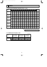
SYMBOL
[LEGEND]
NAME SYMBOL NAME SYMBOL NAME
Connection Terminal<L1/L2-Phase>
R/S
Connector<Connection for Option>
SS
CNMNT
Connector
<Connected to Optional M-NET Adapter Board>
Switch<Model Select>
SW6
Switch
SW9
X51, X52
Relay
SYMBOL
M-NET ADAPTER
NAME
TB7
CN5
CND
CN2M
SW1
SW11
Terminal Block<M-net connection>
Connector<Transmission>
Connector<Power Supply>
Connector<M-NET communication>
Switch<Status of communication>
Switch<Address setting : 1st digit>
SW12
LED1
LED2
LED3
LED4
LED5
Switch<Address setting : 2nd digit>
LED<Power Supply : DC5V>
LED<Connection to Outdoor Unit>
LED<Transmission : Sending>
LED<Transmission : Recelving>
LED<Power Supply : DC12V>
LED1,LED2
LED<Operation Inspection Indicators>
P. B.
C. B.
CNF1
(WHT)
MF1
MS
3~
7
1
TRANS
CNDC
(PNK)
3
1
TH7/6
(RED)
63H
(YLW)
TH3
(WHT)
TH4
(WHT)
TH7 TH6 TH3 TH4
412121
31
t
°
t
°
t
°
t
°
63H
LEV-A
(WHT)
LEV-A
M
LED1
LED2
61
CNVMNT
(WHT)
31
CNDM
(WHT)
CN51
(WHT)
3151
CNMNT
(WHT)
CNM
(WHT)
51
3
5
SW7
SW6SW1
SW9
CN31
1
w1w1
SW5SW8SW4 SWP
14
X51
CNS
(WHT)
CNAC
(WHT)
SS
(WHT)
21S4
(GRN)
X52
F1
F2
F4
F3
21
43
21S4
31
13 13
CN4
(WHT)
12
2
CN52C
(RED)
2
2
1
CN2
(WHT)
71
5
CN5
(WHT)
31
LED2
SW1
SW11
SW12
LED3
LED4
TB7
LED1
LED5
2
1
CND
(WHT)
CN2M
(WHT)
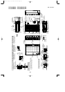
M-NET SUBSTRATE
M-NET
ABS
When M-NET adapter is connected
5
3
5
1
WHT
U
LI EI NI
LO NO
E2
E3
N. F.
2
2
1
3
1
1
3
2
1
2
CN5
(RED)
CNAC1
(WHT)
CNAC2
(RED)
CN52C
(BLK)
52C
RED
U
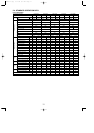
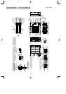
POWER SUPPLY
208 / 230V 60Hz
INDOOR
UNIT
TB1
L1 L2 GR S1 S2 S3
RED
BLU
YLW
GRN
ORN
BRN
CY2
CY1
CB1 CB2 CB3
U
V
TH8
IPM
W
R
S
CN3
(WHT)
CN2
(WHT)
CN4
(WHT)
CN5
(RED)
1
7
1
2
1
2
1
2
2
2
5
t
°
WHT
RED
PFC
RED
WHT
RED
WHT
ACL
MS
3~
BLK
WHT
RED
U
V
W
MC
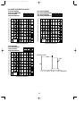
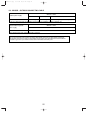
PUZ only
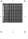
123456
OFF
ON
PUZ-A18N
MODEL SW6
w1 MODEL SELECT
SW5
-
5.6
123456
OFF
ON
PUY-A12N
PUY-A18N
123456
78
78
78
OFF
ON
123456
OFF
ON
123456
OFF
ON
123456
OFF
ON
w2
w2. SW5-1 to 4 : Function switch
wUse copper supply wires.
PUZ-A18NHA2 PUZ-A18NHA2-BS PUY-A12/18NHA2 PUY-A12/18NHA2-BS
7
WIRING DIAGRAM
OCH429--1.qxp 07.11.20 9:17 AM Page 16