


14
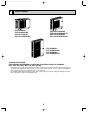
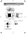
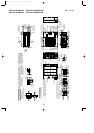
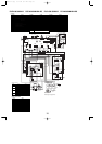
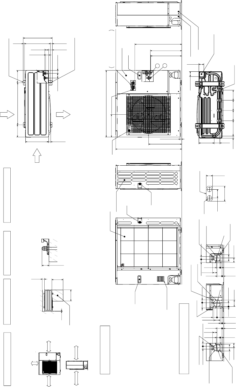
PUZ-A24/30/36NHA2 PUZ-A24/30/36NHA2-BS Unit : mm<inch>
PUY-A24/30/36NHA2 PUY-A24/30/36NHA2-BS
Min. 10mm
<3/8>
Min. 10mm
<3/8>
Min. 100mm
<3-15/16>
Min. 500mm
<19-11/16>
100mm
Min.
<3-15/16>
500mm
Min.
<19-11/16>
500mm
Min.
<19-11/16>
10mm
Min.
<3/8>
Service space
Max.
30mm<1-3/16>
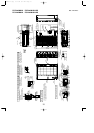
FOUNDATION
<Foundation bolt height>
31<1-7/32>
74<2-19/32>
40<1-9/16>
When installing the conduit,
set the attachment to the
inner side of each panel.
1/2 Conduit attachment
2-
[
22.2<7/8>
330 <13>
175 <6-7/8>
600 <23-5/8>
175 <6-7/8>
53 <2-3/32>
28 <1-3/32> 370 <14-9/16>
19 <3/4>
56 <2-7/32>
45 <1-25/32>
42 <1-21/32>66 <2-5/8>
417 <16-13/32>
2-U Shaped notched hole
(Foundfation Bolt M10<W3/8>)
Side Air Intake
Rear Air Intake
Air outlet
2-12o36oval hole
(Foundation Bolt M10<W3/8>)
30 <1-3/16>
Side Air Intake
Handle
Rear piping cover
Front piping cover
81<3-3/16>
219 <8-5/8>
145
<5-23/32>
220
<8-21/32>
30 <1-3/16>
145
<5-23/32>
71 <2-13/16>
71 <2-13/16>
145
<5-23/32>
Bottom piping hole
(Knockout)
Drain hole
(5-
[
33<1-5/16>)
Handle
Handle
Rear Air Intake
Air Intake
670 <26-3/8>
*1 443<17-7/16>
*1 447<17-19/32>
322 <12-11/16>
950 <37-13/32>
473 <18-5/8>
943 <37-1/8>
23<29/32>
2
1
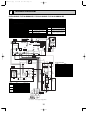
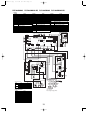
Handle
Handle
Service panel
Earth terminal
Left . . . Power supply wiring
Reight . . Indoor/Outdoor wiring
Terminal Block
63<2-1/2>
73<2-7/8>
75
<2-31/32>
40 <1-9/16>
92<3-5/8>
92<3-5/8>
27<1-1/16>23<29/32>
55<2-3/16>
19<3/4>
Conduit hole
(2-
[
27<1-1/16>Knockout)
Right trunking hole
(Knockout)
Right piping hole
(Knockout)
[
92
<
3-5/8>
45<1-25/32>
65<2-9/16>
92<3-5/8>
40 <1-9/16>
63
<2-1/2>
23<29/32>
73<2-7/8>
55<2-3/16>
27<1-1/16>
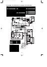
Conduit hole
(2-
[
27<1-1/16>Knockout)
Front trunking hole
(Knockout)
Front piping hole
(Knockout)
[92
<3-5/8>
40 <1-9/16>45<1-25/32>
63<2-1/2>
73<2-7/8>23<29/32
55<2-3/16>
27<1-1/16>
92<3-5/8>
65<2-9/16>
Conduit hole
(2-
[
27<1-1/16>Knockout)
Rear trunking hole
(Knockout)
Rear piping hole
(Knockout)
[
92
<3-5/8>
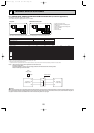
FREE
Piping and wiring connections
can be made from 4 directions:
front, right, rear and below.
Dimensions of space needed
for service access are
shown in the below diagram.
Please secure the unit firmly
with 4 foundation (M10<W3/8>)
bolts. (Bolts and washers must
be purchased locally.)
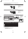
The diagram below shows a
basic example.
Explantion of particular details is
given in the installation manuals etc.
1
····Refrigerant GAS pipe connction (FLARE) [15.88(5/8)
2
····Refrigerant LIQUID pipe connection (FLARE) [ 9.52(3/8)
*1···· Indication of STOP VALVE connection location.
Example of Notes
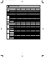
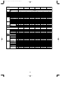
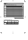
Piping Knockout Hole Details
1 FREE SPACE (Around the unit)
2 SERVICE SPACE
3 FOUNDATION BOLTS
4 PIPING-WIRING DIRECTIONS
OCH429--1.qxp 07.11.20 9:17 AM Page 14