


15
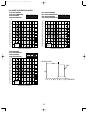
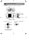
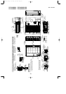
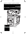
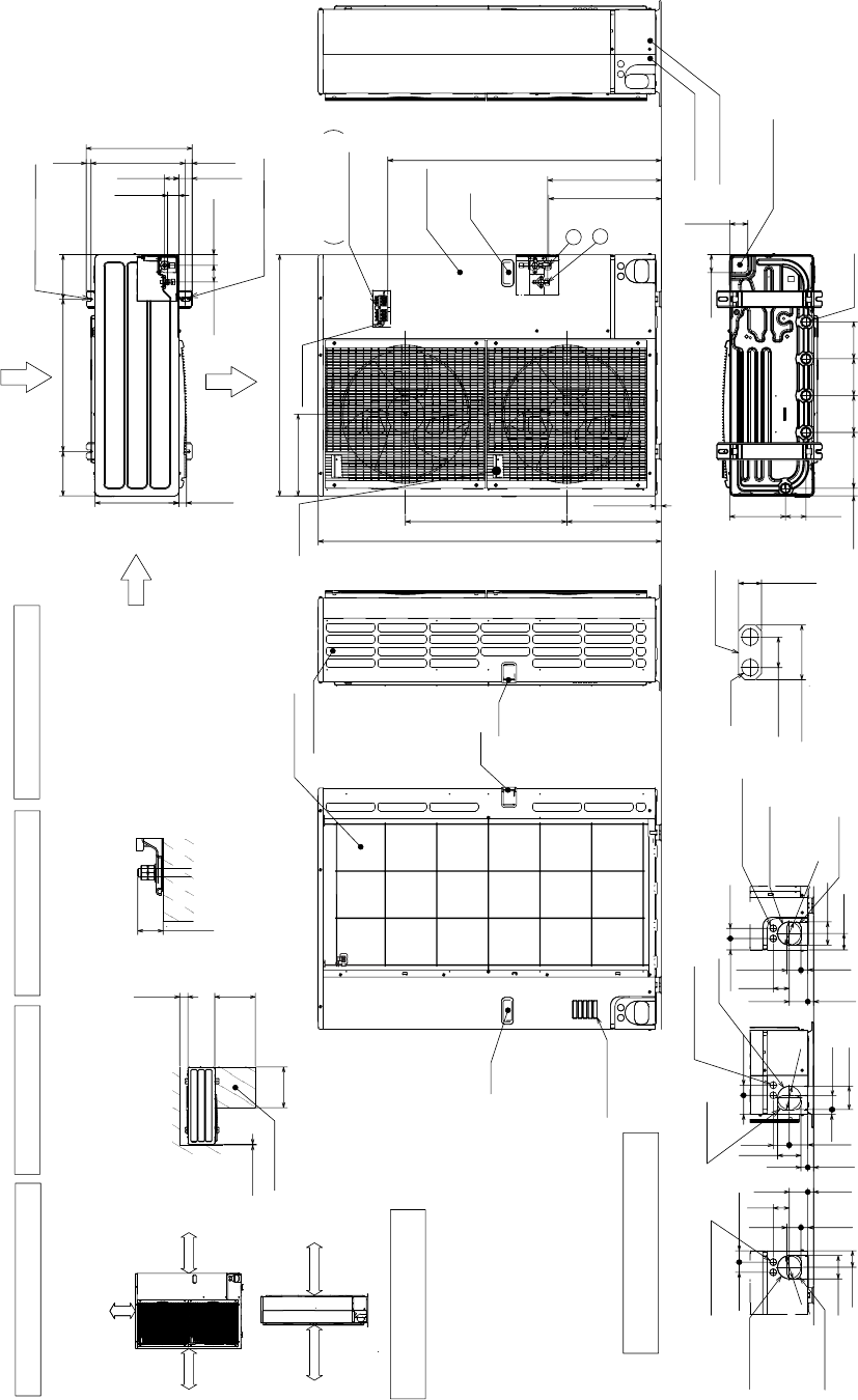
PUZ-A42NHA2 PUZ-A42NHA2-BS Unit : mm<inch>
PUY-A42NHA2 PUY-A42NHA2-BS
Terminal Block
Left ··· Power supply wiring
Right ··· Indoor/Outdoor wiring
Earth terminal
Service panel
Handle
1
2
1350<53-5/32>
23<29/32>
950<37-13/32>
1076<42-3/8>
* 1 447<17-19/32>
* 1 443<17-7/16>
371<14-19/32>
635<25>
322<12-11/16>
Handle
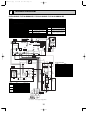
Min. 1000mm
<39-3/8>
Min. 150mm
<5-29/32>
Min. 10mm
<3/8>
Min. 10mm
<3/8>
FREE
Max.
Min.
Min.
Min.
Min.
Handle
Side Air Intake
Front piping cover
Rear piping cover
Air intake
Rear Air Intake
Handle
Handle
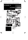
<Foundation bolt height>
Air outlet
Rear Air Intake
Side Air Intake
30mm<1-3/16>
FOUNDATION
150mm
<5-29/32>
500mm
<19-11/16>
500mm
<19-11/16>
10mm<3/8>
Service space
40<1-9/16>
74<2-19/32>
31<1-7/32>
When installing the conduit.
set the attachment to the
inner side of each panel.
2-
[
22.2<7/8>
1/2 Conduit attachment
600<23-5/8>
175
<6-7/8>
175
<6-7/8>
330<13>
417<16-13/32>
42<1-21/32>
66<2-5/8>
53<2-3/32> 56<2-7/32>
45<1-25/32>
19<3/4>
28<1-3/32> 370<14-9/16>
2-U Shaped notched hole
(Foundation Bolt M10<W3/8>)
2-12o36 Oval hole
(Foundation Bolt M10<W3/8>)
30<1-3/16>
45<1-25/32>
40<1-9/16>
65<2-9/16>
92<3-5/8>
27<1-1/16>
55<2-3/16>
23<29/32> 73<2-7/8>
63<2-1/2>
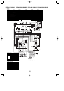
Rear piping hole
(Knockout)
Rear trunking hole
(Knockout)
Conduit hole
(2-[27<1-1/16>Knockout)
[92
<3-5/8>
19<3/4>
55<2-3/16>
92<3-5/8>
75
<2-31/32>
40<1-9/16>
73<2-7/8>
63<2-1/2>
23<29/32> 27<1-1/16>
92<3-5/8>
Right piping hole
(Knockout)
Right trunking hole
(Knockout)
Conduit hole
(2-[27<1-1/16>Knockout)
[92
<3-5/8>
92<3-5/8>
65<2-9/16>
45<1-25/32>40<1-9/16>
27<1-1/16>
55<2-3/16>
23<29/32> 73<2-7/8>
63
<2-1/2>
Front piping hole
(Knockout)
Front trunking hole
(Knockout)
Conduit hole
(2-[27<1-1/16>Knockout)
[92
<3-5/8>
145
<5-23/32>
145
<5-23/32>
220
<8-21/32>
30<1-3/16>
145
<5-23/32>
81<3-3/16>
219<8-5/8>
71<2-13/16>
71<2-13/16>
Bottom piping hole
(Knockout)
Drain hole
5-
[
33<1-5/16>
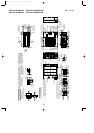
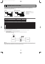
The diagram below shows a
basic example.
Explantion of particular details is
given in the installation manuals etc.
Dimensions of space needed
for service access are
shown in the below diagram.
Please secure the unit firmly
with 4 foundation (M10<W3/8>)
bolts. (Bolts and washers must
be purchased locally.)
1 . . .Refrigerant GAS pipe connction (FLARE) [15.88(5/8)
2 . . .Refrigerant LIQUID pipe connection (FLARE) [ 9.52(3/8)
*1 . . .Indication of STOP VALVE connection location.
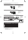
Piping and wiring connections
can be made from 4 directions:
front, right, rear and below.
Example of Notes
1 FREE SPACE (Around the unit)
2 SERVICE SPACE
3 FOUNDATION BOLTS
4 PIPING-WIRING DIRECTIONS
Piping Knockout Hole Details
OCH429--1.qxp 07.11.20 9:17 AM Page 15