


7
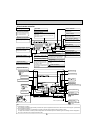
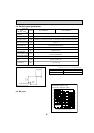
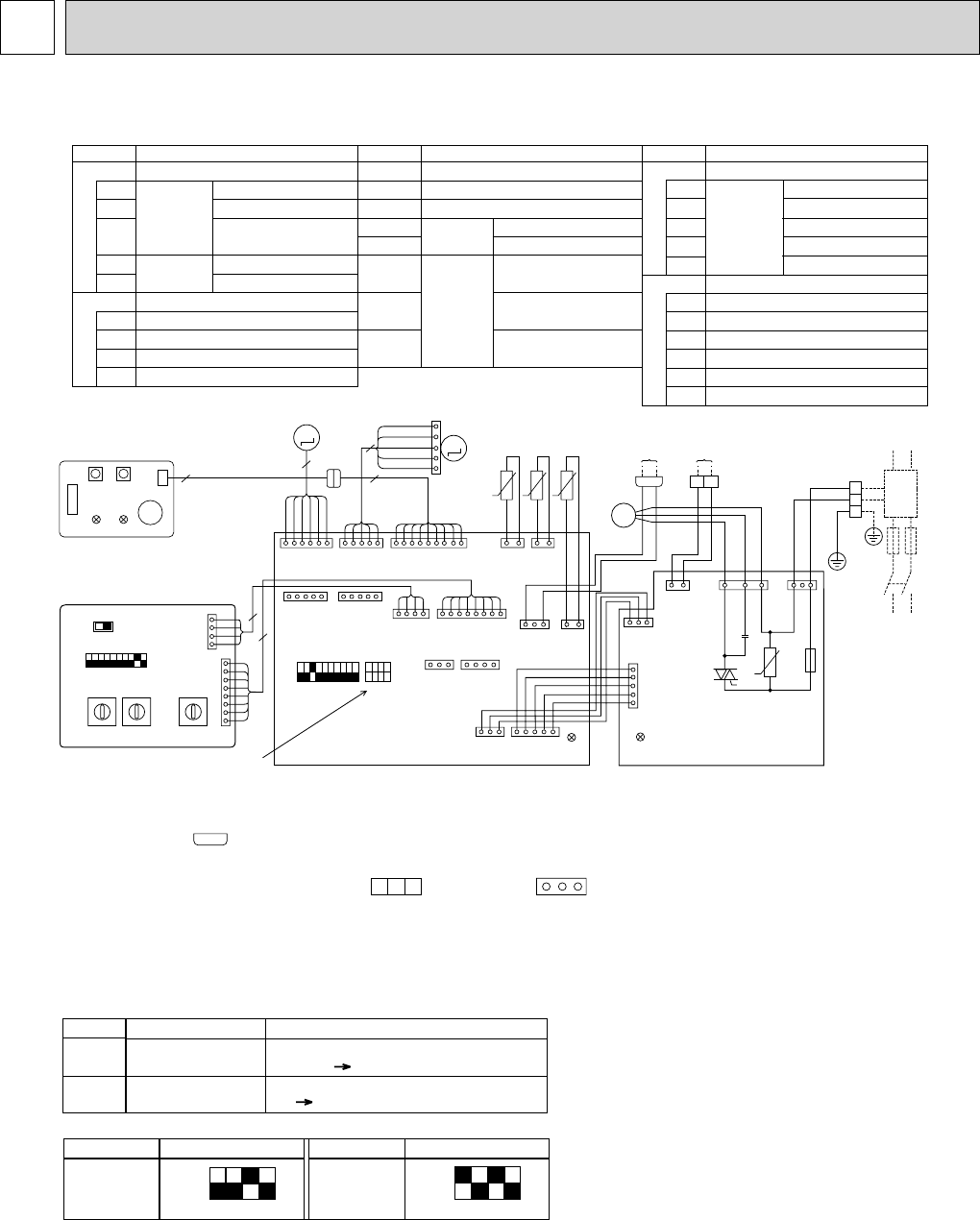
WIRING DIAGRAM4
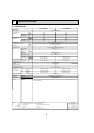
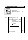
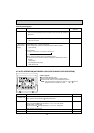
Mark Meaning
LED1
Main power supply
Main power supply (indoor unit: 208-230V)
power on lamp is lit
Function
LED on indoor board for service
ON
OFF
1234
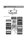
MODELS SW2
P06
ON
OFF
1234
MODELS SW2
P08
<Fig. 1>
LED2
Power supply for
MA-Remote controller
Power supply for MA-Remote controller
on lamp is lit
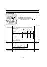
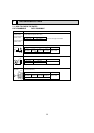
Legend
Symbol
I.B
CN32
CN51
CN52
SW2
SW2
SW3
TH21
TH22
Remote switch
Centrally control
Remote indication,
External heater
Capacity code
Mode selection
Room temp.detection
(32°F/15k
,77°F/5.4k)
Pipe temp.detection/Liquid
(32°F/15k,77°F/5.4k)
Name
Indoor controller board
P. B
W.B
Indoor power board
ZNR Varistor
FUSE
Fuse (6A 250V)
F.C
Fan phase control
MF Fan motor
C1
Capacitor (Fan motor)
MV
Vane motor
LEV
Linear expansion valve
Connector
Switch
Switch
Thermistor
Symbol
TB2
TB5
Power supply
Transmission
Address board
Mode selection
Name
Symbol
Name
Terminal
block
TH23
Pipe temp.detection/Gas
(32°F/15k,77°F/5.4k)
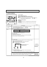
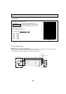
Note
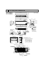
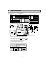
1. At servicing for outdoor unit, always follow the wiring diagram of outdoor unit.
2. In case of using MA-remote controller, please connect MA-remote controller cable in an accessory
to the connector . (Remote controller wire is non-polar.)
3. In case of using M-NET, please connect to TB5 (Transmission line is non-polar.)
4. Symbols used in wiring diagram above are, : terminal block, : connector
5. The setting of the SW2 dip switches differs in the capacity. For the detail, refer to the Fig. 1.
6. Please set the switch SW5 according to the power supply voltage.
Set SW5 to 230V side when the power supply is 230 volts.
When the power supply is 208 volts, set SW5 to 208V side.
12
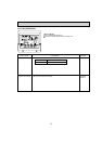
A.B
SW1
SW1
SW5
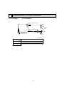
RU
BZ
LED1 LED(Operation indicator:Green)
LED
(Preparation for heating:Orange)
Emergency operation (Heat)
Emergency operation (Cool)
LED2
SW11
SW12
SW14
Voltage selection
Address setting 1s digit
Address setting 10ths digit
Branch No.
Receving unit
Buzzer
Wireless remote controller board
MV
M
RED
WHT
BLU
ORN
YLW
CN5V
VANE
(BLU)
CN52CN51
CN41
CN32
6
5
9
CN60
LEV
(WHT)
BRN
RED
BLU
ORN
YLW
WHT
9
CN3A
MA-
REMOCON
(BLU)
MF
FAN
(GRN)
CND
(RED)
CN2M
M-NET
(BLU)
TO OUTDOOR UNIT
BC CONTROLLER
M-NET REMOTE CONTROLLER
DC24-30V
BREAKER
(16A)
FUSE
(16A)
PULL
BOX
TB2
TO NEXT
INDOOR UNIT
POWER SUPPLY
208/230V 60Hz
RED
RED
WHT
BLK
BLU
GRN /YLW
BLU
BLU
1
TB5
2
TO MA-REMOTE
CONTROLLER
DC8.7-13V
ORN
ORN
ZNR
FUSE
250V
6A
C1
LED1
CN35P
(BLU)
F.C
CN53P
(RED)
CN53M
(RED)
CN35M
(BLU)
LED2
CN29
GAS
(BLK)
CN21
LIQUID
(WHT)
TH23 TH22
CN20
INTAKE
(RED)
TH21
CN81
ADDRESS
(RED)
(RED)
ADDRESS
CN82
CN42
ADDRESS
(RED)
(RED)
ADDRESS
CN43
SW2SW3
123456789
10
1234
ON
OFF
I.B
See Fig.1
SW5
SW1
208V 230V
A.B
W.B
ON
OFF
P.B
4
8
1234567891
4
1
11
112
12
13
2
13
13
146
13
14
56
CN90
WIRELESS
(WHT)
91
141 8
1
1
5
5
8
1
1
5
LED2
CNB
RU
SW2SW1
LED1
BZ
t° t° t°
M
M
1~
LEV
M1M2
U
L1
L2
13
12
1515
<
+
>
GR
<+>Use copper supply wires.
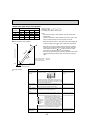
0
1
2
3
4
5
6
7
8
9
A
B
C
D
E
F
0
1
2
3
4
5
6
7
8
9
0
1
2
3
4
5
6
7
8
9
SW14SW11SW12
10ths
DIGIT
1s
DIGIT
BRANCH
No.
0
PKFY-P06NBMU-E PKFY-P08NBMU-E