


PHOTOSOPERATION PROCEDURE
22
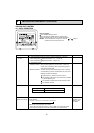
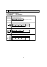
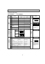
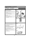
3. REMOVING THE INDOOR CONTROLLER BOARD AND
INDOOR POWER BOARD
(1) Remove the front panel. (Refer to 2)
(2) Remove the electrical box cover (screw 4 × 10).
(Refer to the Photo 2)
INDOOR CONTROLLER BOARD
(1) Disconnect the following connectors on the indoor
controller board.
(connector in front of)
CN60, CN5V, CN90, CN29, CN21
CN42, CN81, CN3A, CN20
(2) Pull out the indoor controller board toward you, then
disconnect the rest of connectors.
CN53M, CN35M (See the Photo 3)
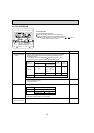
INDOOR POWER BOARD
(1) Disconnect the following connectors on the indoor power
board.
FAN, CN53P, CN35P, CN2M, CND
(2) Remove the earth wire for TAB1.
(3) Pull out the indoor power board toward you.
(See the Photo 3)
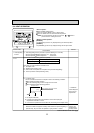
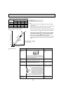
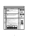
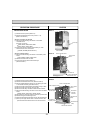
4. REMOVING THE ELECTRICAL BOX
(1) Remove the front panel. (Refer to 2)
(2) Remove the electrical box cover. (See the Photo 2)
(3) Pull the nozzle assembly toward you as opening the catch
of the nozzle assembly. (See the Photo 5)
(4) Disconnect the indoor/outdoor transmission wiring of TB5.
(5) Disconnect the power supply wiring of TB2.
(6) Disconnect the relay connector of MA-remote controller.
(7) Disconnect the following connector on the indoor controller
board.
CN60, CN5V, CN29, CN21, CN90, (CN3A)
(8) Disconnect the connector (FAN) on the indoor power board.
(9) Remove the ground wire fixing screw.
(10) Pull the disconnected lead wire out from the electrical box.
(11) Push up the upper fixture catch to remove the box, then
pull the lower fixture and remove it from the box fixture.
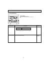
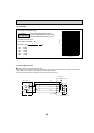
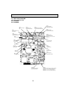
Photo 4
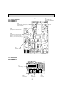
Photo 2
Electrical box cover
Electrical box
Screw cap
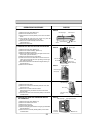
Photo 3
Indoor controller board
Indoor power
board
Electrical box
Ground wire set screw
Linear expansion valve
Terminal block
(TB2)
Terminal block
(TB5)
Indoor power
board
Indoor controller board
Liquid pipe temp.
thermistor (TH22)
Gas pipe temp.
thermistor (TH23)
MA-remote
controller
connector
Room temperature
thermistor cover