


16
6
5
4
3
2
1
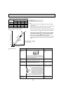
LED1kΩ
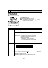
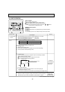
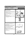
Symptom
Check points
Operation circuit
failure of the micro
processor
Disconnect the connector on the controller board, then con-
nect LED for checking.
When power is turned on, pulse signals will be output for 10
seconds. There must be some defects in the operation circuit
if the LED does not light while the signals are output or keeps
lighting even after the signals stop.
Countermeasures
Exchange the indoor con-
troller board at drive circuit
failure.
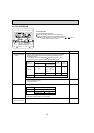
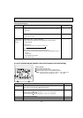
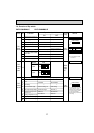
Linear expansion
valve mechanism is
locked.
Valve does not close
completely.
Wrong connection
of the connector or
contact failure
To check the linear expansion valve, operate the indoor unit
in fan mode and at the same time operate other indoor units
in cooling mode, then check the pipe temperature <liquid
pipe temperature> of the indoor unit by the
outdoor multi controller board operation
monitor. During fan operation, linear expan-
sion valve is closed completely and if there
is any leaking, detecting temperature of
the thermistor will go lower. If the detected
temperature is much lower than the tem-
perature indicated in the remote controller,
it means the valve is not closed all the way.
It is not necessary to exchange the linear expansion valve, if
the leakage is small and not affecting normal operation.
Thermistor
(Liquid pipe)
Linear
expansion
valve
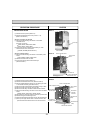
Motor will idle and make a ticking noise when the motor is
operated while the linear expansion valve is locked.
This ticking sound is the sign of the abnormality.
Check the color of lead wire and missing terminal of the con-
nector.
Exchange the linear expan-
sion valve.
Exchange the linear expan-
sion valve.
If large amount of refriger-
ant is leaked, exchange
the linear expansion valve.
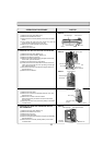
Disconnect the connector
at the controller board,
then check the continuity.
Measure the resistance between each coil (white-red, yellow-
brown, orange-red, blue-brown) using a tester. It is normal if
the resistance is in the range of 200Ω ±10%.
Short or breakage
of the motor coil of
the linear expansion
valve
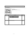
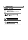
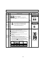
Output
(Phase)
Output
[1
1
ON
[2
ON
[3
OFF
[4
OFF
2
OFF
ON
ON
OFF
3
OFF
OFF
ON
ON
4
ON
OFF
OFF
ON
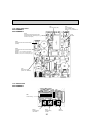
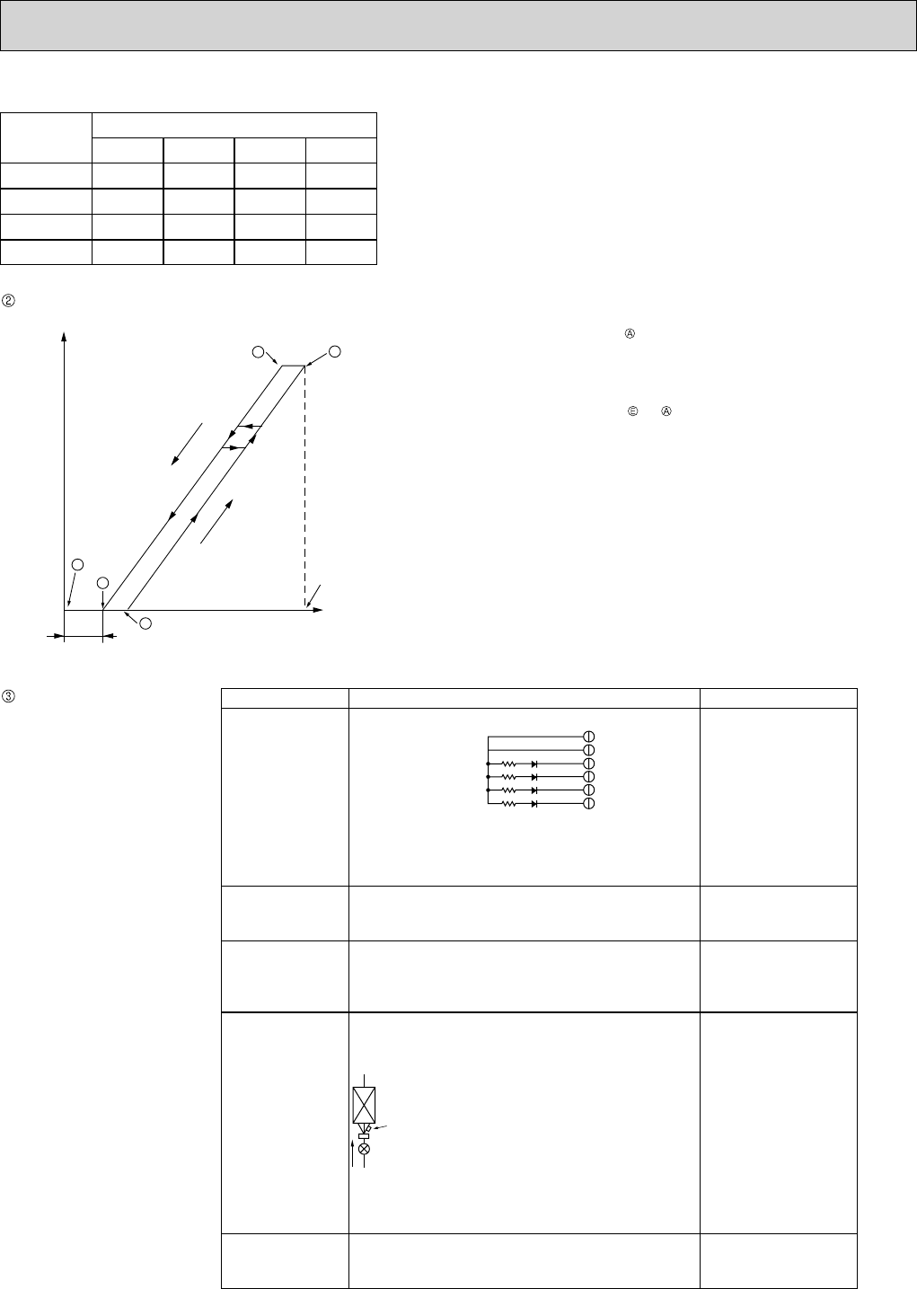
<Output pulse signal and the valve operation>
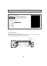
Linear expansion valve operation
Trouble shooting
D
A
E
B
C
Open
Open
Extra tightening (200~800 pulse)
Pulse number
Outdoor unit R410A model : 1400 pulse
Outdoor unit R22 model : 2000 pulse
Opening a valve all the way
Close
Close
Valve position (capacity)
Closing a valve : 1 → 2 → 3 → 4 → 1
Opening a valve : 4 → 3 → 2 → 1 → 4
The output pulse shifts in above order.
Note:
• When linear expansion valve operation stops, all output phase
become OFF.
• At phase interruption or when phase does not shift in order, motor
does not rotate smoothly and motor will lock and vibrate.
• When the switch is turned on, 2200 pulse closing valve signal will
be sent till it goes to point in order to define the valve position.
• When the valve moves smoothly, there is no sound or vibration
occurring from the linear expansion valves, however, when the
pulse number moves from to or when the valve is locked,
more sound can be heard than in a normal situation.
• Sound can be detected by placing the ear against the screw driver
handle while putting the screw driver tip to the linear expansion
valve.