


55
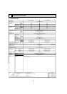
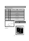
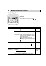
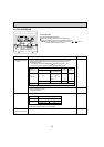
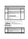
Parts name
Service Ref.
Symbol
TH21
TH22
TH23
FUSE
MF
C1
MV
LEV
TB2
TB5
TB15
Resistance 30°F/15.8k, 50°F/9.6k, 70°F/6.0k, 80°F/4.8k, 90°F/3.9k, 100°F/3.2k
Resistance 30°F/15.8k, 50°F/9.6k, 70°F/6.0k, 80°F/4.8k, 90°F/3.9k, 100°F/3.2k
Resistance 30°F/15.8k, 50°F/9.6k, 70°F/6.0k, 80°F/4.8k, 90°F/3.9k, 100°F/3.2k
250V 6A
4-Pole Output 8W / PS4N8-KB
1.2 × 440V
MSFBC20 DC12V
(L1, L2, GR) 250V 20A
(M1, M2, S) 250V 20A
(1, 2) 250V 10A
Liquid pipe thermistor
Gas pipe thermistor
PKFY-P06NBMU-E PKFY-P08NBMU-E
Room temperature
thermistor
Fuse
(Indoor controller board)
Fan motor
(with thermal fuse)
Fan motor capacitor
Vane motor
(with limit switch)
Linear expansion valve
Power supply terminal
block
Transmission terminal
block
DC12V Stepping motor drive
Port :3.2 (0~2000pulse)
MA remote controller
terminal block
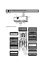
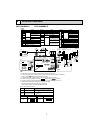
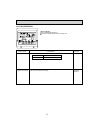
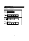
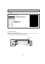
* Measured in anechoic room.
3.3 ft.
(1m)
Measurement location
PKFY-P06NBMU-E
PKFY-P08NBMU-E
32-33-35-36
Sound level dB (A)
Sound level at anechoic room : Low-Middle2-Middle1-High
Service Ref.
32-33-35-36
3.3 ft.
(1m)
2-2. Electrical parts specifi cations
2-3. Sound levels
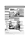
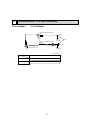
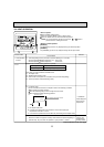
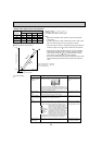
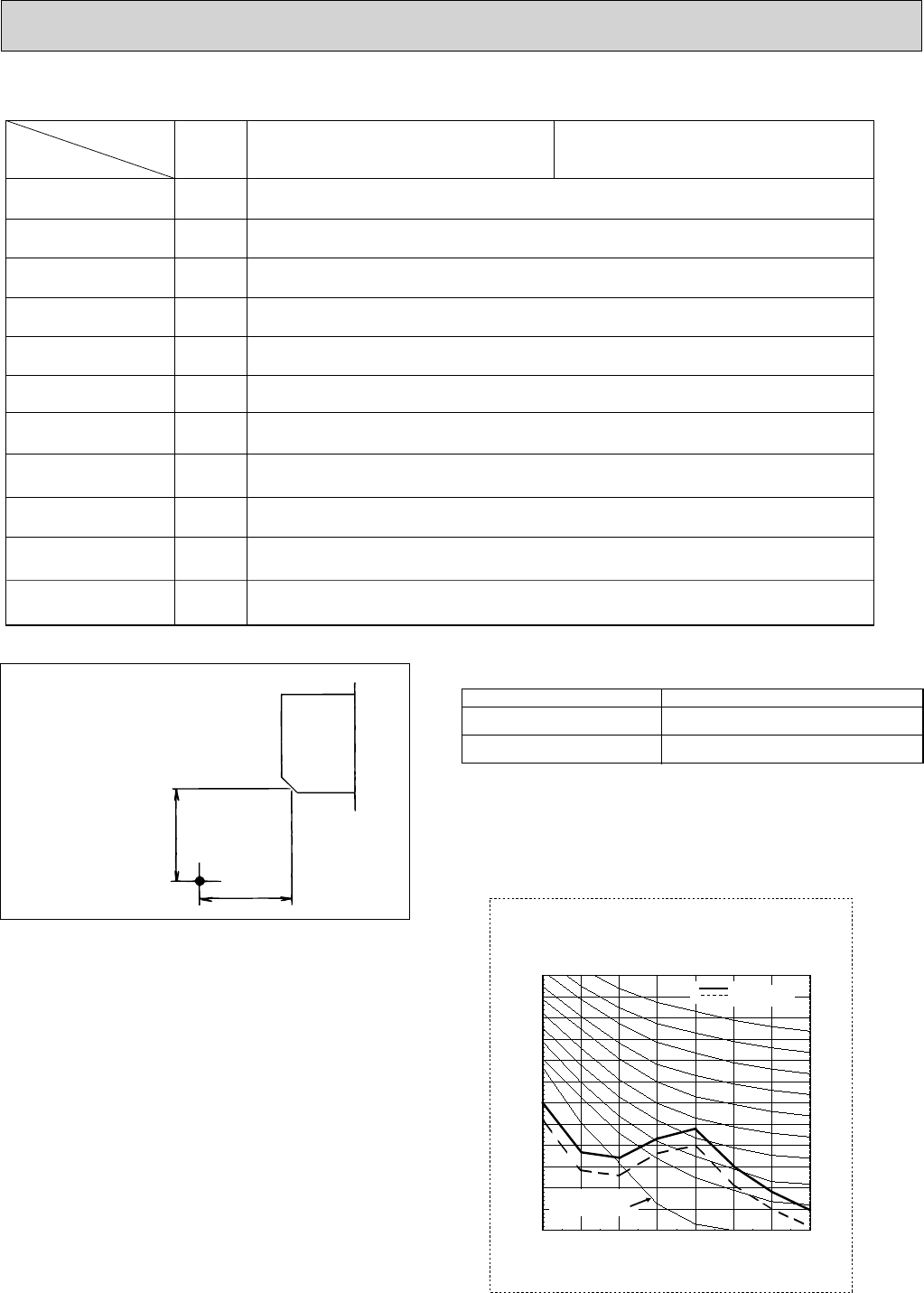
2-4. NC curve
PKFY-P06/08NBMU-E
External static pressure : 0Pa
Power source : 208,230V, 60Hz
OCTAVE BAND PRESSURE LEVEL (dB) 0dB = 20
MPa
OCTAVE BAND CENTER FREQUENCIES(Hz)
Approximate minimum
audible limit on
continuous noise
10.0
15.0
20.0
25.0
30.0
35.0
40.0
45.0
50.0
55.0
60.0
65.0
70.0
63 125 250 500 1k 2k 4k 8k
NC60
NC50
NC40
NC30
NC20
High speed
Low speed