


19
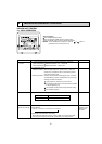
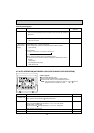
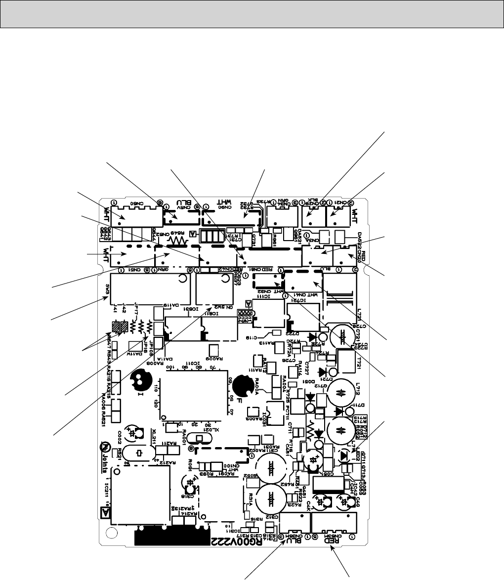
7-3. TEST POINT DIAGRAM
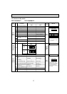
7-3-1. Indoor controller board
PKFY-P06NBMU-E
PKFY-P08NBMU-E
CN3A
Connected to the
MA-Remote controller
Between 1 to 3 8.7-13V DC
(Pin1 (+))
CN29
Pipe temperature
thermistor/Gas (TH23)
CN21
Pipe temperature
thermistor/Liquid (TH22)
CN90
Connected to the wireless
remote controller board (W.B)
CN60
Linear expansion valve
output (LEV)
SW3
Mode selection
CN51
Centrally control
SW2
Capacity setting
CN52
Remote indication
External heater
CN5V
Vane motor output
(MV)
CN20
Room temperature
thermistor (TH21)
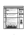
CN53M
Connected to the indoor power board (CN53P)
Between 1 to 2 24-30V DC (non-polat)
Between 3 to 5 12.5-13.7V DC (Pin3 (+))
Between 4 to 5 11.5-12.7V DC (Pin4 (+))
CN35M
Connected to the indoor
power board (CN35P)
LED2
Power supply for
MA-Remote controller
CN41
Connector
(HA terminal-A)
CN32
Connector
(Remote switch)
J41, J42
Wireless remote controller
Pair No. setting
JP105
Model setting
CN81
Connected to the
address board (CN82)
CN42
Connected to the
address board (CN43)