23
5-2-2 Adjusting the measured temperature/humidity values
When the adjustment of the measured values is necessary because of the location of the sensor, follow the
procedures below.
Note: The present measurement value or the adjusted measurement value are not displayed until the connection settings of the
AI controller are completed.
When the AI controller is registered for the first time, click the [Save Settings] button to send setting data, and click
[Function 1]-Measurement] to display the screen again.
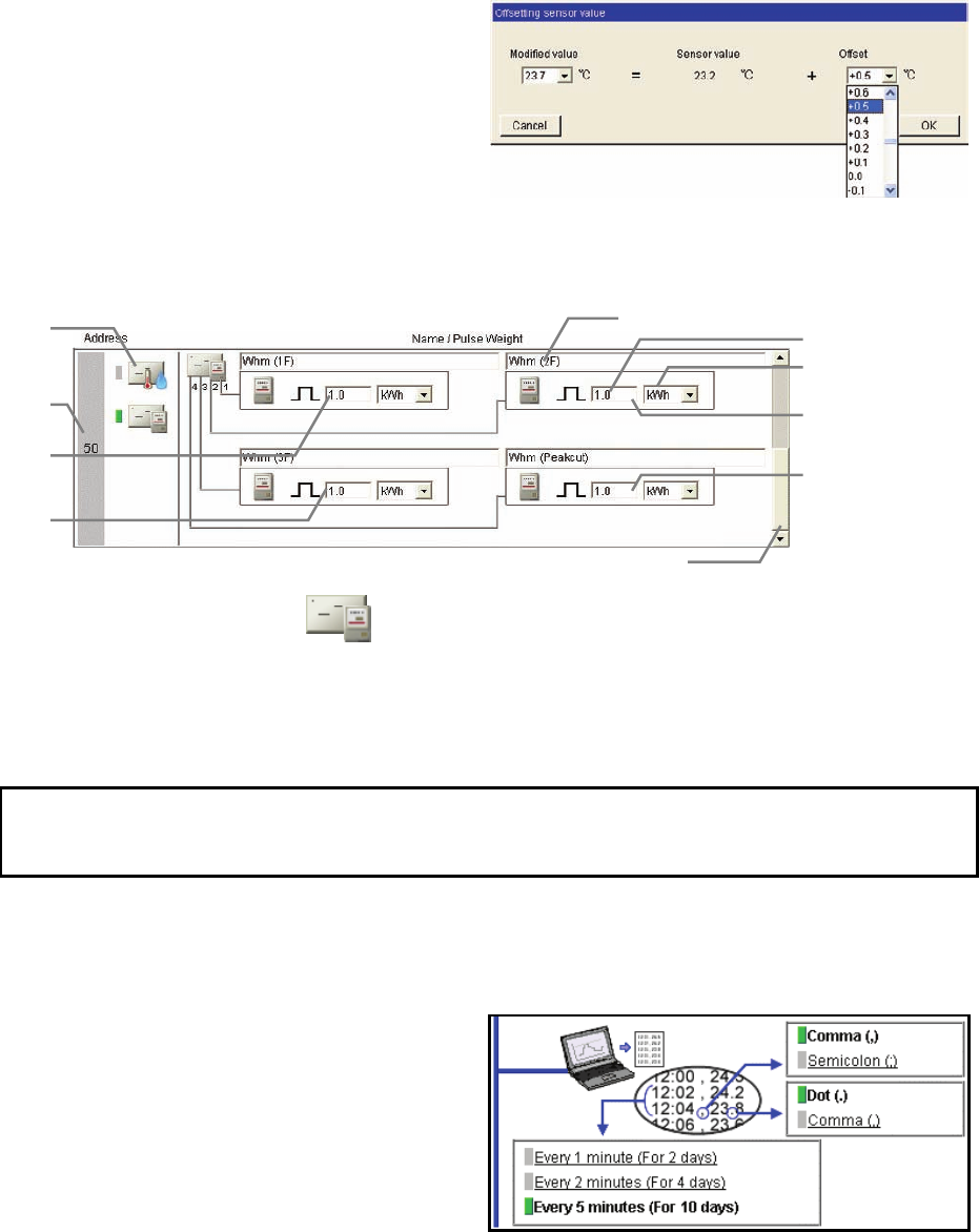
(1) Click the [Set offset] in the [Setting details] section.
(2) Select the adjustment value in the [Offset] pulldown
or select the value to be desired in the [Modified
value] pulldown.
The adjustable range is between -10.0ºC and
+10.0ºC (-18.0ºF and +18.0ºF), -10.0% and +10.0%.
5-2-3 Registering PI controllers for measurement by meters
System settings for measurement meters can be made. Up to four meters can be connected to one PI
controller (PAC-YG60MCA).
(1) Use the scroll bar, and select the address to which the PI controller is connected.
(2) Select the icon of the PI controller (
) in the column of items to be measured.
Note: To disconnect the PI controller, click the icon of the PI controller that has been selected. The icon will be in unselected state.
(3) Enter the name of the meter.
(4) Enter the value per pulse (measurement value per pulse) of the connected meter, and select the unit.
Note: The measurement unit can be selected between [kWh], [m3], [MJ] and [--(no unit)].
Note: Select the blank in the measurement unit pulldown for the meter not to be used.
5-2-4 Setting the trend data format
The data format to be used when the trend graph data of the measured value is downloaded or is sent by
e-mail can be set.
(1) Select the separator character between [Comma
( , )] and [Semicolon ( ; )].
(2) Select the decimal point character between [Period
( . )] and [Comma ( , )].
(3) Select the trend data interval between [1 minute (for
2 days)], [2 minutes (for 4 days)], and [5 minutes (for
10 days)]. The period of time that the trend graph
can be displayed on the trend graph screen varies
depending on the data interval.
Address
Items to be
measured
Value per pulse
Measurement unit
Meter name
Setting details o
f
sensor 1
Setting details o
f
sensor 3
Setting details o
f
sensor 3
Setting details o
f
sensor 4
Scroll ba
r
Note: Set the value per pulse according to the measurement meter to be used. To check that the setting is correctly made, first
check both the values measured by the measurement meter and by the measurement controller, and after a certain time,
check that the both values have increased at equal increments. (The value measured by the measurement controller can be
checked on the browser for the administrator.)


