


-3-
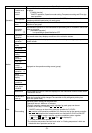
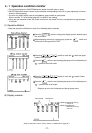
The central controller is supplied power from the PAC-SC50KUA Power Supply Unit via the M-NET transmission line and
DC power line. The DC power between the PAC-SC50KUA Power Supply Unit and the central controller should be 10m
or less. The central controller allows to be connected to M-NET transmission line at any position. (M-NET transmission
line is the central control line which connects TB7 terminal of the outdoor unit)
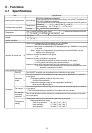
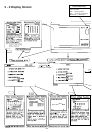
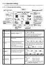
[ 2 ] System configuration setup and maintenance function
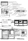
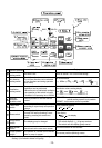
[ 3 ] Other
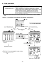
1. Registration can be made for the indoor units, local remote controllers and slave system controllers in the same
2. Group name may be specified. ( Names may include alphanumeric characters.)
3. Group name may be copied.
4. Setting of group configuration and specifying the group name may be performed as long as power is being supplied
5. System configuration data setting in the central controller can be deleted at once if necessary when replacing cir-
to the central controller. This mean that setting can be performed before the central controller is installed at
the site, before installation of individual units is completed or while the power supply to some units is cut off.
cuits wired board, etc.
All unit address (indoor, outdoor, etc.) can be displayed for individual refrigerant system on the refrigerant system
monitor screen. This information is useful for checking the installation, such as address setting, transmission line
connection and power supply connection.
Setting can be performed for indoor units interlocked with a ventilation unit.
If even one of the indoor units interlocked with ventilation have started to operate, the ventilation will be activated.
1. A log of the last 64 malfunction massage, in the order in which they occurred, can be monitored.
2. The data and time the malfunction occurred, the address of unit where it occurred, the error code and the ad-
3. All malfunction logged in the memory of the central controller and indoor unit can be reset at once.
dress of unit that detected the malfunction are displayed.
Displays normal operation/all OFF/malfunction status for the entire system.
This switch allows turning all of the unit in the system ON or OFF at once.
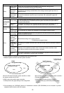
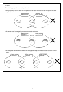
The combined maximum distance between the outdoor units and the central controller, and between the outdoor units
and farthest indoor units connected to the same refrigerant system or their remote controller, may be extended up
500 meters.
Therefore, even if the total distance is made longer by installing the outdoor units all in row, there will be no problem
so long as the above maximum total distance limitation is not exceeded.
(Normal operation/all OFF/malfunction status is indicated by the lamp being lit, not lit or blinking respectively)
group.
And also registration can be made for the ventilation such as OA processing unit.
(1) Setup for system configuration
(2) Refrigerant system monitor
(3) Interlocked group setting
(4) Malfunction log monitor
(1) Overall statues display lamp
(2) Collective ON/OFF switch
(3) Power supply wiring
(4) M-NET transmission line