


34
Installation & Operation Manual
6 Hydronic piping
System water piping methods
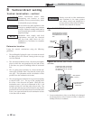
The Knight is designed to function in a closed loop pressurized
system not less than 12 psi. A temperature and pressure
gauge is included to monitor system pressure and outlet
temperature and should be located on the boiler outlet.
It is important to note that the boiler has a minimal
amount of pressure drop and must be figured in when
sizing the circulators. Each boiler installation must have
an air elimination device, which will remove air from
the system. Install the boiler so the gas ignition system
components are protected from water (dripping, spraying,
etc.) during appliance operation for basic service of circulator
replacement, valves, and others.
Observe a minimum of 1/4 inch (6 mm) clearance around all
un-insulated hot water pipes when openings around the
pipes are not protected by non-combustible materials.
Low water cutoff device
On a boiler installed above radiation level, some states and
local codes require a low water cutoff device at the time of
installation.
Chilled water system
If the boiler supplies hot water to heating coils in air handler
units, flow control valves or other devices must be installed to
prevent gravity circulation of heater water in the coils during
the cooling cycle. A chilled water medium must be piped in
parallel with the heater.
Freeze protection
Freeze protection for new or existing systems must use glycol
that is specially formulated for this purpose. This includes
inhibitors, which prevent the glycol from attacking the
metallic system components. Make certain to check that
the system fluid is correct for the glycol concentration and
inhibitor level. The system should be tested at least once
a year and as recommended by the producer of the glycol
solution. Allowance should be made for the expansion of the
glycol solution in the system piping.
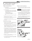
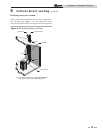
3. Install purge and balance valve or shutoff valve and drain
on system return to purge air out of each zone.
4. Install a backflow preventer on the cold feed make-up water
line.
5. Install a pressure reducing valve on the cold feed make-
up water line, (15 psi nominal). Check temperature and
pressure gauge (shipped separately), which should read a
minimum pressure of 12 psi.
6. Install a circulator as shown on the piping diagrams in this
section. Make sure the circulator is properly sized for the
system and friction loss.
7. Install an expansion tank on the system supply. Consult the
tank manufacturer’s instruction for specific information
relating to tank installation. Size the expansion tank for the
required system volume and capacity.
8. Install an air elimination device on the system supply.
9. Install a drain valve at the lowest point of the system.
Note: The boiler cannot be drained completely of water
without purging the unit with an air pressure of 15 psi.
10. This appliance is supplied with a relief valve sized in
accordance with ASME Boiler and Pressure Vessel Code,
Section IV (“Heating Boilers”). Pipe the discharge of the
safety relief valve to prevent injury in the event of pressure
relief. Pipe the discharge to a drain. Provide piping that is
the same size as the safety relief valve outlet. Never block
the outlet of the safety relief valve.
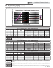
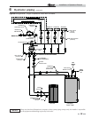
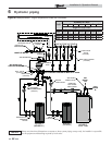
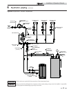
*See the piping illustrations included in this section, FIG.’s 6-4
thru 6-10 for suggested guidelines in piping the Knight boiler
with either zone valves or circulator pumps.
*Please note that these illustrations are
meant to show system piping concept only,
the installer is responsible for all equipment
and detailing required by local codes.
Use only inhibited propylene glycol
solutions, which are specifically formulated
for hydronic systems. Ethylene glycol is
toxic and can attack gaskets and seals used
in hydronic systems.
ƽ WARNING
NOTICE
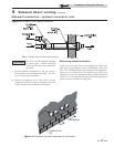
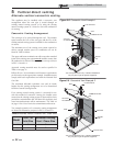
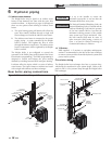
General piping information
Basic steps are listed in this section along with illustrations on
the following pages (FIG.’s 6-4 thru 6-10), which will guide
you through the installation of the Knight boiler (reference
FIG.’s 6-2A and 6-2B).
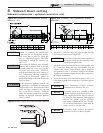
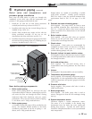
1. Connect the system return marked “Inlet”.
2. Connect the system supply marked “Outlet”.
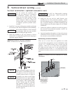
ƽ WARNING
The relief valve, tee and any necessary fittings
are shipped in the install kit with the boiler
and are to be field installed (FIG. 6-1).
CAUTION
The Knight boiler is capable of servicing
multiple temperature loop systems. It is the
responsibility of the installer to protect the
loops with lower temperature requirements
from higher temperatures that may be
required by other loops.