


35
Installation & Operation Manual
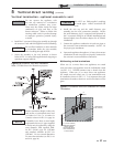
Relief valve and temperature and
pressure gauge installation
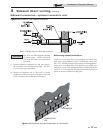
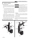
Basic steps are listed below to guide you through the
installation of the relief valve and the temperature and
pressure (T & P) gauge provided with the unit.
1. Install the tee with the 3/4 inch fitting positioned
vertically and on the top as shown in FIG. 6-1.
2. Install the relief valve into the 3/4 inch fitting of the tee
installed in Step 1 (FIG. 6-1).
3. Install a field provided close nipple and tee with the
fitting positioned vertically on the top on the
downstream side of the relief valve (see FIG. 6-1).
4. Install the temperature and pressure gauge provided with
the unit into the top fitting of the tee (a bushing may be
necessary) installed in Step 3 (FIG. 6-1).
6 Hydronic piping (continued)
TEMPERATURE &
PRESSURE GAUGE
TEE W/FITTING ON TOP
(FIELD PROVIDED)
CLOSE NIPPLE
(FIELD PROVIDED)
TEE WITH 3/4” FITTING ON TOP
CLOSE NIPPLE
RELIEF VALVE
Figure 6-1 Relief Valve / T & P Installation
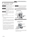
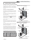
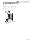
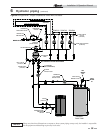
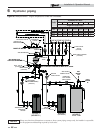
Near boiler piping components
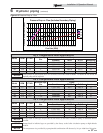
1. Boiler system piping:
Boiler system piping MUST be sized per the pipe
requirements listed in Table 6A. Reducing the pipe size
can restrict the flow rate through the boiler, causing
inadvertent high limit shutdowns and poor system
performance. Flow rates are based on 20 feet of piping,
4 - 90° elbows, and 2 - fully ported ball valves.
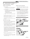
2. Boiler system pump:
A Grundfos UPS26-99F pump will be provided by the
factory (for standard altitude models) as the boiler
circulation pump based on 20 feet of piping, 4 - 90°
elbows, and 2 - fully ported ball valves.
Knight boilers are capable of controlling a variable
speed boiler circulator. Variable speed circulators
MUST be sized to meet the specified minimum flow
requirements listed in FIG. 6-3 on page 37 at full
speed.
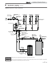
3. Domestic hot water circulating pump:
Field supplied. The pump MUST be sized to meet
the specified minimum flow requirements listed in
FIG. 6-3. Consult the indirect water heater operating
guide to determine flow characteristics for the selected
product used.
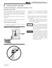
4. Boiler isolation valves:
Field supplied. Full port ball valves are required.
Failure to use full port ball valves could result in a
restricted flow rate through the boiler.
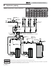
5. Check valves:
Field supplied. Check valves are recommended for
installation as shown in FIG.’s 6-4 thru 6-10. Failure to
install check valves could result in a reverse flow
condition during pump(s) off cycle.
6. Domestic indirect hot water isolation valves:
Field supplied. Full port ball valves are required. Failure
to use full port ball valves could result in a restricted flow
rate through the boiler.
7. Anti-scald mixing valve:
Field supplied. An anti-scald mixing valve is
recommended when storing domestic hot water above
115°F.
8. Unions:
Field supplied. Recommended for unit serviceability.
9. Temperature and pressure gauge:
Factory supplied. The temperature and pressure gauge is
shipped loose. It is the responsibility of the contractor to
install the temperature and pressure gauge on the boiler
water outlet.
10. Pressure relief valve:
Factory supplied. The pressure relief valve is sized to
ASME specifications.
11. Boiler purge valve:
Field supplied. The boiler purge valve is used to
remove entrapped air from the heat exchanger during
start-up.
12. System temperature sensor:
Lochinvar supplies a system temperature sensor.
The sensor is to be installed in the heating loop
downstream from the boiler hot water piping and
heating loop junction. Typically the sensor will be
located far enough downstream to sense system diluted
water temperature.