


26
Installation & Operation Manual
4 Sidewall direct venting
Sidewall termination – optional concentric vent
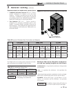
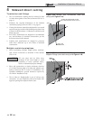
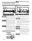
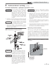
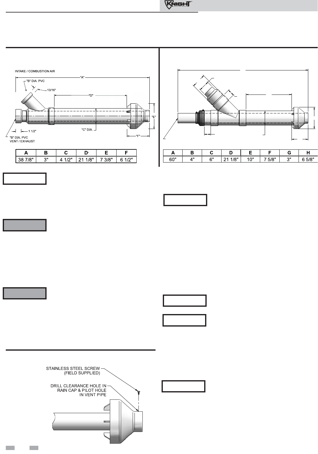
Figure 4-9 Concentric Vent Dimensional Drawing -
Models 81 - 211
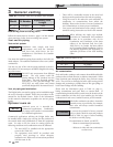
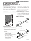
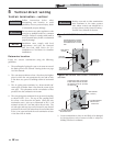
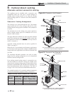
Instead of cementing the smaller pipe
to the rain cap, a field-supplied stainless
steel screw may be used to secure the
two (2) components together when field
disassembly is desired for cleaning (see
FIG. 4-11).
When using the alternate screw assembly
method, drill a clearance hole in the rain
cap and a pilot hole in the vent pipe for
the screw size being used. Failure to
drill adequate holes may cause cracking of
PVC components, allowing combustion
products to be recirculated. Failure to
follow this warning could result in personal
injury or death.
Do not operate the appliance with the rain
cap removed or recirculation of combustion
products may occur. Water may also collect
inside the larger combustion air pipe and
flow to the burner enclosure. Failure to
follow this warning could result in product
damage or improper operation, personal
injury, or death.
Figure 4-11 Rain Cap to Vent Pipe Alternate Assembly
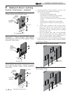
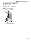
6. Install the Y concentric fitting and pipe assembly through
the structure’s hole from an inside wall.
Do not allow insulation or other materials to
accumulate inside the pipe assembly when
installing through the hole.
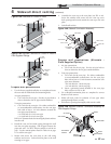
7. Install the rain cap and small diameter pipe assembly into
the Y concentric fitting and large pipe assembly from an
outside wall. Ensure small diameter pipe is bottomed
and cemented in the Y concentric fitting for #CVK3003
installations and fastened tightly into the rubber adapter for
#CVK3007 installations.
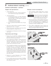
8. Secure the assembly to the structure as shown in FIG. 4-12
using field-supplied metal strapping or equivalent support
material.
Ensure termination location clearance
dimensions are as shown in FIG. 4-6.
If assembly needs to be extended to allow
sidewall thickness requirement, the two (2)
pipes supplied in the kit may be replaced
by using the same diameter, field-supplied
SDR-26 PVC (D2241) pipe for CVK3003
and standard schedule 40 PVC for CVK3007.
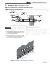
Do not extend dimension D* more than 60
inches (see FIG.’s 4-9 and 4-10).
NOTICE
ƽ WARNING
ƽ WARNING
NOTICE
NOTICE
NOTICE
If assembly depth needs to be reduced,
dimension D can be as short as possible.
NOTICE
"B" DIA. PVC
VENT / EXHAUST
"A"
"H" DIA.
"D"
"E"
"F"
"G"
3"
(76 MM)
"C" DIA.
"B" DIA.
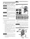
Figure 4-10 Concentric Vent Dimensional Drawing -
Model 286