


Installation & Operation Manual
Table 3A Vent Pipe, and Fittings
All vent pipe materials and fittings must comply with the following:
Item Material
Standards for installation in:
United States Canada
Vent pipe and
fittings
PVC Plastic Pipe, Schedules 40, 80, & 120 ANSI/ASTM D1785
CPVC and PVC venting must be ULC-S636
Certified. IPEX is an approved manufacturer
in Canada supplying vent material listed to
ULC-S636.
PVC Plastic Pipe Fittings, Schedule 40 ANSI/ASTM D2466
PVC Plastic Pipe Fittings, Schedule 80 ANSI/ASTM D2467
PVC - DWV Pipe and Fittings ANSI/ASTM D2665
CPVC Plastic Pipe, Schedule 40 & 80 ANSI/ASTM F441
CPVC Plastic Pipe Fittings, Schedule 80 ANSI/ASTM F439
AL29-4C UL1738 ULC-S636
NOTICE: DO NOT USE CELLULAR (FOAM) CORE PIPE
Approved Stainless Steel Vent Manufacturers
Make Model
ProTech Systems (Simpson Dura-Vent Co.) FasNSeal Vent / FasNSeal Flex* Vent
Z-Flex (Nova Flex Group) Z-Vent
Heat Fab (Selkirk Corporation) Saf-T Vent
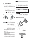
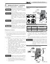
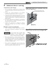
6. Priming and Cementing:
a. Handle fittings and pipes carefully to prevent
contamination of surfaces.
b. Apply a liberal even coat of primer to the fitting
socket.
c. Apply a liberal even coat of primer to the pipe end to
approximately 1/2" beyond the socket depth.
d. Apply a second primer coat to the fitting socket.
e. While primer is still wet, apply an even coat of
approved cement to the pipe equal to the depth of
the fitting socket.
f. While primer is still wet, apply an even coat of
approved cement to the fitting socket.
g. Apply a second coat of cement to the pipe.
h. While the cement is still wet, insert the pipe into the
fitting, if possible twist the pipe a 1/4 turn as you insert
it. NOTE: If voids are present, sufficient cement was
not applied and joint could be defective.
i. Wipe excess cement from the joint removing ring or
beads as it will needlessly soften the pipe.
3 General venting (continued)
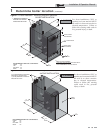
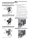
PVC/CPVC air intake/vent connections
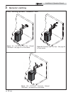
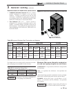
1. Combustion Air Intake Connector (FIG.’s 3-9 and 3-10) - Used to provide combustion air directly to the unit from
outdoors. A fitting is provided on the unit for final connection. Combustion air piping must be supported per guidelines
listed in the National Mechanical Code, Section 305, Table 305.4 or as local codes dictate.
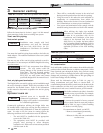
2. Vent Connector (FIG.’s 3-9 and 3-10) - Used to provide a passageway for conveying combustion gases to the outside. A
transition fitting is provided on the unit for final connection. Vent piping must be supported per the National Building Code,
Section 305, Table 305.4 or as local codes dictate.
3” CPVC PIPE SUPPLIED WITH BOILER
MUST BE USED FOR VENT CONNECTION
NOTE: CPVC VENT PIPE AND VENT FITTINGS MUST BE USED IN CLOSET
AND ALCOVE INSTALLATIONS.
VENT
AIR
Figure 3-9 Near Boiler PVC/CPVC Venting Models
81 - 211
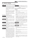
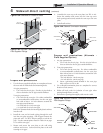
4” CPVC PIPE SUPPLIED WITH BOILER
MUST BE USED FOR VENT CONNECTION
NOTE: CPVC VENT PIPE AND VENT FITTINGS MUST BE USED IN CLOSET
AND ALCOVE INSTALLATIONS.
Figure 3-10 Near Boiler PVC/CPVC Venting Model 286
*Use of FasNSeal Flex smooth inner wall vent is to be used in vertical or near vertical sections only, taking precaution to ensure
no sagging occurs of the vent system. Connect to the FasNSeal rigid vent using specially designed adapters and sealing method,
see manufacturer’s instructions.
17