


31
Installation & Operation Manual
5 Vertical direct venting (continued)
Vertical termination – optional concentric vent
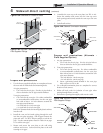
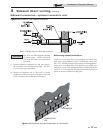
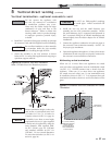
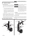
Figure 5-6 Concentric Vent Roof Installation
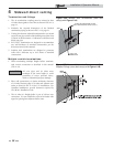
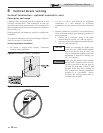
Ensure termination height is above the
roof surface or anticipated snow level
(12 inches in U.S.A. or 18 inches in
Canada) as shown in FIG. 5-4, page 30.
If assembly is too short to meet height
requirement, the two (2) pipes supplied
in the kit may be replaced by using the
same diameter, field supplied SDR-
26 PVC (D2241) pipe for CVK3003
and standard schedule 40 PVC for
CVK3007. Do not extend dimension
D* more than 60 inches (see FIG.’s 4-9
and 4-10, page 26).
CAUTION
DO NOT use field-supplied couplings
to extend pipes. Airflow restriction will
occur.
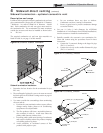
6. Install the rain cap and the small diameter pipe
assembly into the roof penetration assembly. Ensure
the small diameter pipe is cemented and bottomed in
the Y concentric fitting for #CVK3003 installations and
fastened tightly into the rubber adapter for #CVK3007
installations.
7. Cement the appliance combustion air and vent pipes to
the concentric vent termination assembly. See FIG. 5-6
for proper pipe attachment.
8. Operate the appliance through one (1) heat cycle to ensure
combustion air and vent pipes are properly connected to
the concentric vent termination connections.
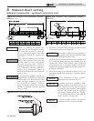
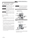
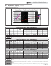
Multiventing vertical terminations
When two (2) or more direct vent appliances are vented
near each other, each appliance must be individually vented
(see FIG. 5-7). NEVER common vent or breach vent this
appliance. When two (2) or more direct vent appliances
are vented near each other, two (2) vent terminations may
be installed as shown in FIG. 5-7. It is important that vent
terminations be made as shown to avoid recirculation of flue
gases.
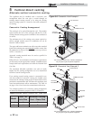
12”
MINIMUM
12” (18” FOR CANADA)
MINIMUM CLEARANCE
ABOVE HIGHEST
ANTICIPATED SNOW
LEVEL. MAXIMUM OF
24” ABOVE ROOF.
COMBUSTION
AIR (TYPICAL)
Figure 5-7 Concentric Vent and Combustion Air Vertical
Termination
Do not operate the appliance with
the rain cap removed or recirculation
of combustion products may occur.
Water may also collect inside the larger
combustion air pipe and flow to the
burner enclosure. Failure to follow this
warning could result in product damage
or improper operation, personal injury,
or death.
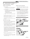
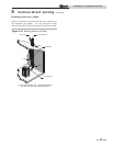
4. Install the Y concentric fitting pipe assembly up through
the structure’s hole and field supplied roof boot/flashing.
Do not allow insulation or other materials
to accumulate inside the pipe assembly
when installing through the hole.
5. Secure the assembly to the roof structure as shown
below in FIG. 5-6 using field supplied metal strapping or
equivalent support material.
ƽ WARNING
NOTICE
NOTICE
NOTICE
Note: CVK3003 shown for illustration purposes.