


59
Installation & Operation Manual
Check flame and combustion (continued) Set space heating operation
Determine controlling sensor
For space heating systems, the temperature control can be
based on one of three sensors; the inlet, outlet, or system
supply sensor. The SMART SYSTEM control is programmed
at the factory to control the temperature of the outlet
sensor. The control will automatically switch to the system
supply sensor once it is connected. If it is desired to base
the temperature control on the inlet sensor, the appropriate
parameter must be changed in the control. See the Knight
Boiler Service Manual for a detailed explanation of this
procedure.
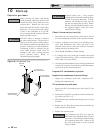
Verify space heat circulator mode
The Space Heating Mode controls both the system (primary)
pump (if connected), and the boiler (secondary) pump.
When the SMART SYSTEM control receives a space heating
call for heat, it turns on the system pump. If the boiler is not
heating an indirect DHW (Domestic Hot Water) tank, and
the set point is not met, it also turns on the boiler pump.
After the space heating call for heat ends, the system pump
continues to run for a short period of time. The system
pump can be programmed to run continuously, except
during outdoor shutdown. If the boiler pump was running,
it continues to run for a short period of time as well. These
pump delays are factory set to 30 seconds. If different delays
are desired, the appropriate parameters in the control must
be changed. See the Knight Boiler Service Manual for a
detailed explanation of this procedure.
Adjust set point temperature
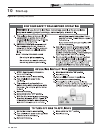
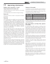
Table 10A Flue Products Chart
8. Once the combustion analysis is complete, test the safety
shutoff device by turning the manual shutoff switch to
the OFF position and ensuring that the boiler shuts
down and registers an alarm. Turn the manual shutoff
switch to the ON position, reset the control, and return
to Service Mode.
9. Turn the main power off to the boiler and replace the flue
temperature sensor into the flue pipe connection.
10. Place the boiler back into normal operation.
You must replace the flue gas temperature
sensor to prevent flue gas spillage into
the room. Failure to comply could
result in severe personal injury, death, or
substantial property damage.
ƽ WARNING
Natural Gas Propane
CO
2
O
2
CO
2
O
2
8.0% - 10% 3.0% - 6.5% 9.0% - 11% 4.1% - 6.9%
10 Start-up (continued)
Please note that the brackets ([]) denote
screen status.
NOTICE
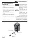
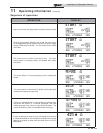
4. Place the boiler into the active position by pressing the
RIGHT SELECT [ON] key (FIG. 11-1, page 67).
5. Locate the pinhole button below the RESET button on
the display board (FIG. 11-1). Insert a thin wire (such as
a paper clip) into the hole and press the button once and
hold for 5 seconds to place the boiler into Service Mode.
In Service Mode the boiler will fire at ignition speed and
will then modulate up to full fire.
6. Insert the probe from a combustion analyzer into the hole
left by the removal of the flue temperature sensor.
7. Once the boiler has modulated up to full fire, measure
the combustion. The values should be in the range listed
in Table 10A below. The CO levels should be less than
150 ppm for a properly installed unit.
If the combustion is not within the specified range,
reference the Troubleshooting Section of the Knight
Boiler Service Manual for possible causes and corrective
actions.
Please note that the brackets ([]) denote
screen status.
NOTICE
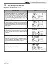
The NAVIGATION dial may be used during normal
operation to adjust the space heating and tank set point
temperatures.
1. From the Status Screen press the NAVIGATION dial.
2. Turn the NAVIGATION dial counterclockwise to select
the appropriate set point.
3. Press the NAVIGATION dial to adjust the temperature.
4. Once the desired temperature is displayed, press the
RIGHT SELECT [SAVE] key.
5. If necessary repeat Steps 3 and 4 to make adjustments to
additional set points.
6. Press the RIGHT SELECT [HOME[ key to upload the
changes.
7. If the RIGHT SELECT [SAVE] key is not pressed, the
new settings will be discarded.