


51
Installation & Operation Manual
8 Field wiring (continued)
Thermostat
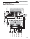
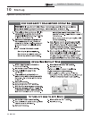
1. Connect the room thermostats or end switches (isolated
contact only) to room thermostat 1, 2, or 3, as shown in
FIG. 8-3.
2. Install the thermostat on the inside wall away from
influences of drafts, hot or cold water pipes, lighting
fixtures, television, sunlight, or fireplaces.
3. Thermostat anticipator (if applicable):
a. If connected directly to boiler, set for 0.1 amps.
b. If connected to relays or other devices, set to match
total electrical power requirements of connected
devices. See device manufacturers’ specifications
and thermostat instructions for details.
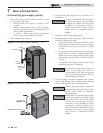
Outdoor temperature sensor
1. Mount the sensor on an exterior wall, shielded from
direct sunlight or flow of heat or cooling from other
sources.
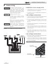
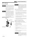
2. Route sensor wires through a knockout at the rear of the
boiler (see FIG. 8-2).
3. Connect outdoor temperature sensor (FIG. 8-3) to the
outdoor sensor terminals on the connection board to
enable outdoor reset operation of the Knight boiler. If
fixed temperature operation is required, do not install
outdoor sensor.
3. If the TST20015 is not compatible with the indirect tank,
a tank thermostat can be used to control the boiler. The
tank thermostat should be installed per the manufacturers
instructions and wired to the DHW Thermostat terminals
on the Low Voltage Connection Board.
Louver relay
If louvers need to operate when the boiler fires, they can be
controlled by this output. Connect these terminals to a 24 vac
relay coil, which is wired to operate the louvers (FIG. 8-3).
Louver proving switch
When the operation of the louvers needs to be verified before
the boiler fires, remove the jumper wire from these terminals
and connect them to the normally open contacts on its proving
switch (FIG. 8-3).
High gas pressure switch
If a switch is provided to detect excessive gas pressure, remove
the jumper wire from the terminals on the connection board,
and then connect them to its normally closed contacts (FIG.
8-3).
Low gas pressure switch
1. If a switch is provided to detect low gas pressure, remove the
jumper wire from the terminals on the connection board
and connect them to its normally open contacts (FIG. 8-3).
2. If both a high and low gas pressure switch is used, connect
their respective contacts in series, and connect them to the
terminals on the connection board (FIG. 8-3).
Failure to use the correct sensor may result
in the tank temperature being either above
or below the set point. Failure to consult
the manufacturer of the indirect tank,
when the Squire is not used, may result in
decreased performance or the risk of scald
injury.
ƽ WARNING
DHW thermostat
Connect storage indirect water heater (DHW) thermostat
(FIG. 8-3) to the DHW thermostat terminals on the
connection board. If a tank sensor is connected (see DHW
Tank Sensor below) the tank thermostat is ignored.
DHW tank sensor
1. By installing a tank sensor, the SMART SYSTEM control
can perform the tank thermostat function. The SMART
SYSTEM control automatically detects the presence of
this sensor and generates a DHW call for heat when
the tank temperature drops 6°F (3°C) below the tank
set point and finishes the call for heat when the tank
temperature reaches the tank set point.
2. The tank sensor included with the Lochinvar Squire
Indirect DHW tank (TST20015) is the only sensor
suitable for use with the SMART SYSTEM control.
Connect the sensor leads to the Tank Sensor terminals on
the Low Voltage Connection Board (FIG. 8-3). Consult
the tank manufacturer for application and performance
when used with any other indirect tank.
Variable speed system pump
If a variable speed pump is used in the primary loop, and
a 0-10V signal is available from the pump speed control,
this signal can be used by the SMART SYSTEM control to
anticipate changes in the building heat load. By connecting this
0 - 10V signal to the 0 - 10V SYS PUMP IN terminals, the boiler
(or cascade) can modulate up and down as the primary flow
increases and decreases.
Boiler pump speed output
This 0 - 10V output is available to control the speed of a variable
speed boiler pump. The SMART SYSTEM control will vary the
speed of this pump in order to maintain a minimum T across
the heat exchanger, as well as prevent high limit lockouts when
the flow in the primary loop is extremely low. Connect this
output to the 0 - 10V input on the boiler pump speed control.
Rate output
This output provides a 0 - 10V signal that is proportional to the
firing rate of the boiler. This may be used by a BMS system to
monitor the actual rate of the boiler.