


7
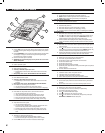
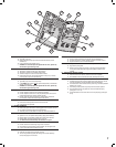
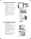
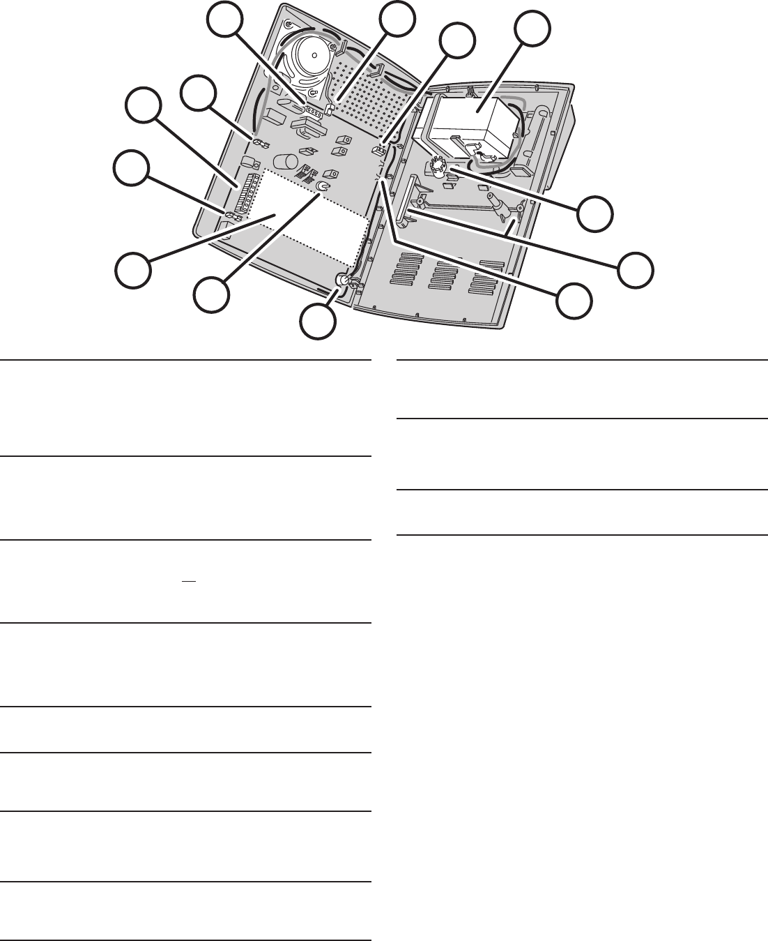
10 AUXILIARY FUSE
★ Type 2AG, 1-amp fuse.
★ Protects the external relay output when used with wet contacts (12 VDC
switched out).
★ Fuse will blow when load exceeds 1 amp.
✎ WARNING: For continued protection against the risk of fi re, replace only
with the same type and rating of fuse.
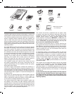
11 MAIN TERMINAL BLOCK
★ Terminals for connection to the plug-in AC transformer.
★ Terminals for connection to an external siren speaker.
★ Automation Output to connect to an automation controller.
★ External relay output for “wet” contacts (switched 12 volts) or “dry” contacts
(normally open 1 amp @ 24 volts maximum).
12 BATTERY FUSE
★ Type 2AG, 3-amp fuse for the backup battery.
★ If the POWER light is fl ashing and the optional backup battery is installed and
charged, check this fuse.
✎ WARNING: For continued protection against the risk of fi re, replace only
with the same type and rating of fuse.
13 TELEPHONE TERMINAL BLOCK
★ Provides telephone connections for the digital communicator.
★ Provides telephone connection for voice prompted telephone remote control
(optional VB-2 digital voice response module required).
★ Provides seized ring and tip connections for local telephone instruments.
Communicator will disconnect local telephones while on-line.
14 INTERNAL SPEAKER CONNECTOR
★ Connects the internal speaker to the Console circuit board.
★ 2-pin connector, non-polarized.
15 ANTENNA TERMINALS
★ Antenna and ground terminals for receiving signals from the system's sensors.
★ Pre-wired to the Console's internal wire dipole antenna.
★ Alternately connects to the Model LA-P local whip and remote antenna kit.
16 OPTIONAL BACKUP BATTERY
★ Space for 12-volt, 1.2 amp/hour backup battery. (Highly recommended.)
★ Backup battery is automatically charged and monitored by the Console.
★ Backup battery can power the Console for up to 6 hours.
★ UL NOTE: Normal estimated battery life should be 3 to 4 years.
17 WIRING ACCESS HOLE
★ Provides access to recessed wiring trough in base of Console.
★ Route cables for power, telephone, external speaker, etc. through this hole.
★ Loop for zip-tie strain relief provided next to hole.
18 WALL-MOUNT SLOTS
★ Used when mounting Console recessed in the wall.
★ Two mounting brackets (supplied) slide through slots and are retained by
screws, clamping the unit to the wall.
19 RADIO TEST POINTS
★ Used to monitor the Console's radio receiver during troubleshooting.
★ Provides connection for an audio amplifi er to listen to the receiver's output.
★ Helpful to determine sources of radio interference.
20 MICROPHONE (WITH MODEL VB-2 INSTALLED ONLY)
★ High sensitivity microphone.
★ Detects room audio when communicator is reporting to the Central Station
in 2-way audio mode (Model VB-2 digital voice synthesis module must be
installed).
21 ANNUNCIATOR VOLUME CONTROL
★ Varies the volume of the advisory tones that come from the speaker.
★ Does not affect internal or external sirens (they are always full volume).
22 DIGITAL VOICE SYNTHESIS MODULE (OPTIONAL)
★ The Model VB-2 gives the Consoles's digital communicator listen-only, manual
2-way and full duplex 2-way audio capability with the Central Station.
★ The module allows remote command of the system using a standard pushbutton
telephone, on or off site.
★ The module provides optional voice prompts from the Console’s speaker.
★ Units programmed for two-way duplex can still be controlled manually by
pressing the “1” or “3” key.
★ The Central Station can now return the unit to two-way duplex by pressing the
“8” key.
10
11
12
22
13
14
21
20
15
16
17
18
19