


Page 29
XP14 SERIES
auto−reset switch closes when the compressor casing
temperature falls to 151−187°F (66°C−86°C), and the
compressor is re−energized. This single−pole, single−throw
(SPST) bi−metallic switch is wired in series with the 24V Y
input signal to control compressor operation.
Crankcase Thermostat (S40) (−036, −042, −048 and
−060 Units Only)
The reference models are equipped with a 70 watt, belly
band type crankcase heater. HR1 prevents liquid from
accumulating in the compressor. HR1 is controlled by a
thermostat located on the liquid line. When liquid line
temperature drops below 50° F the thermostat closes
energizing HR1. The thermostat will open, de−energizing
HR1 once liquid line temperature reaches 70° F .
Defrost Thermostat (S6)
The defrost thermostat is located on the liquid line between
the check/expansion valve and the distributor. When
defrost thermostat senses 42°F (5.5°C) or cooler, the
thermostat contacts close and send a signal to the defrost
control to start the defrost timing. It also terminates defrost
when the liquid line warms up to 70°F (21°C).
Bi−Flow Liquid Line Filter Drier
The unit is equipped with a large−capacity biflow filter drier
which keeps the system clean and dry. If replacement is
necessary, order another of the same design and capacity.
The replacement filter drier must be suitable for use with
HFC−410A refrigerant.
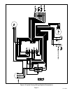
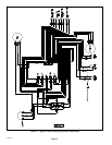
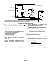
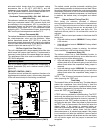
Defrost System
The XP14 defrost system includes two components: a
defrost thermostat (S6) and a defrost control (CMC1)
(figure 15).
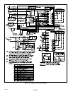
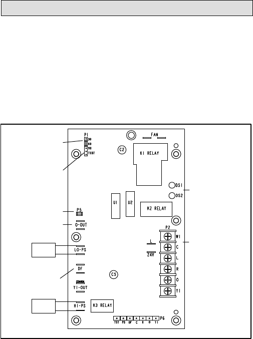
DEFROST CONTROL (CMC1)
The defrost control includes the combined functions of a
time/temperature defrost control, defrost relay, diagnostic
LEDs and terminal strip for field wiring connections.
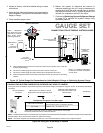
24V TERMINAL
STRIP
CONNECTIONS
DIAGNOSTIC
LEDS
HIGH PRESSURE
SWITCH
TEST
PINS
P1 − FIELD SELECT
TIMING PINS
REVERSING
VALVE
DEFROST
THERMOSTAT
LOW PRESSURE
SWITCH
P5 −
COMPRESSOR
DELAY PINS
S4
S87
Figure 24. Outdoor Unit Defrost Control (CMC1)
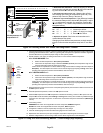
The defrost control provides automatic switching from
normal heating operation to defrost mode and back. When
the defrost thermostat is closed, the control accumulates
compressor run time at 30, 60 or 90 minute field adjustable
intervals. When the selected compressor run time interval
is reached, the defrost relay is energized and defrost
begins.
Defrost Control Timing Pins (P1)
Each timing pin selection provides a different
accumulated compressor run time period for one defrost
cycle. This time period must occur before a defrost cycle
is initiated. The defrost interval can be adjusted to 30
(T1), 60 (T2), or 90 (T3) minutes (see figure 24). The
maximum defrost period is 14 minutes and cannot be
adjusted.
NOTE Ċ Defrost control part number is listed near the P1
timing pins.
S Units with defrost control 100269−02: Factory default
is 60 minutes
S Units with defrost control 100269−04: Factory default
is 90 minutes
If the timing selector jumper is missing, the defrost
control defaults to a 90−minute defrost interval.
Compressor Delay (P5)
The defrost control has a field−selectable function to
reduce occasional sounds that may occur while the unit is
cycling in and out of the defrost mode.
S Units with defrost control 100269−02: The compressor
will be cycled off for 30 seconds going in and out of the
defrost mode when the compressor delay jumper is
removed.
S Units with defrost control 100269−04: The compressor
will be cycled off for 30 seconds going in and out of the
defrost mode when the compressor delay jumper is
installed.
NOTE Ċ The 30-second compressor feature is ignored
when jumpering the TEST pins.
Time Delay
The timed-off delay is five minutes long. The delay helps to
protect the compressor from short-cycling in case the
power to the unit is interrupted or a pressure switch opens.
The delay is bypassed by placing the timer select jumper
across the TEST pins for 0.5 seconds.
Test Mode (P1)
A TEST option is provided for troubleshooting. The TEST
mode may be started any time the unit is in the heating
mode and the defrost thermostat is closed or jumpered. If
the jumper is in the TEST position at power−up, the control
will ignore the test pins. When the jumper is placed across
the TEST pins for two seconds, the control will enter the
defrost mode. If the jumper is removed before an
additional 5−second period has elapsed (7 seconds total),
the unit will remain in defrost mode until the defrost
thermostat opens or 14 minutes have passed. If the jumper
is not removed until after the additional 5−second period
has elapsed, the defrost will terminate and the test option
will not function again until the jumper is removed and
re−applied.