


Page 23
XP14 SERIES
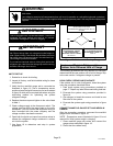
WARNING
Electric Shock Hazard. Can cause injury or death. Unit must be grounded in accordance with national and
local codes.
Line voltage is present at all components when unit is not in operation on units with single-pole contactors.
Disconnect all remote electric power supplies before opening access panel. Unit may have multiple power
supplies.
Unit Start−Up
IMPORTANT
If unit is equipped with a crankcase heater, it should be
energized 24 hours before unit start−up to prevent
compressor damage as a result of slugging.
IMPORTANT
During installation, service or maintenance, make sure
that copper tubing does not rub against metal edges or
other copper tubing. Care should also be taken to ensure
that tubing does not become kinked. Use wire ties to se-
cure tubing to prevent movement.
Do not secure electrical wires to tubing that carries hot
refrigerant gas. Heat from the tubing may melt the wiring
insulation causing a short circuit.
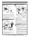
UNIT START−UP
1. Rotate fan to check for binding.
2. Inspect all factory− and field−installed wiring for loose
connections.
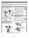
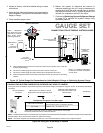
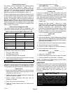
3. Verify that the manifold gauge set is connected as
illustrated in figure 19. Use a temperature sensor
positioned near the liquid line service port as illustrated
in figure 19 which will be required later when using the
subcooling method for optimizing the system
refrigerant charge.
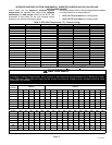
4. Replace the stem caps and tighten to the value listed
in table 1.
5. Check voltage supply at the disconnect switch. The
voltage must be within the range listed on the unit’s
nameplate. If not, do not start the equipment until you
have consulted with the power company and the
voltage condition has been corrected.
6. Open both the liquid and vapor line service valves to
release the refrigerant charge contained in outdoor
unit into the system.
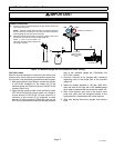
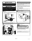
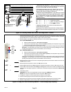
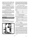
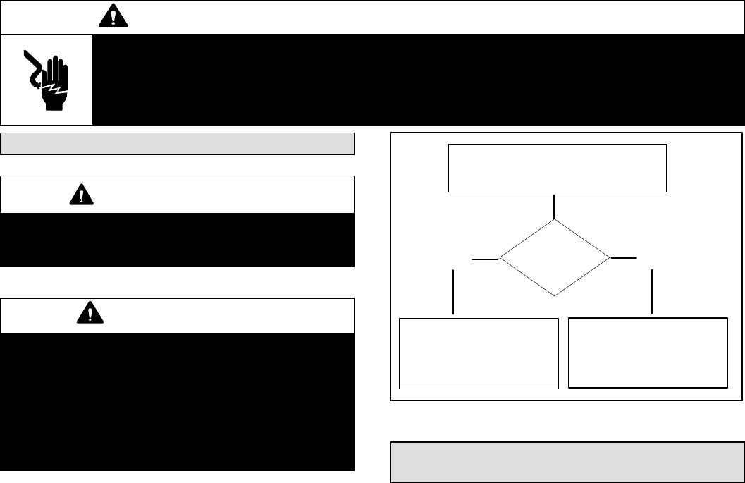
7. Use figure 18 to determine next step in system
preparation.
REFRIGERANT
PRESENT
OPEN BOTH VAPOR AND LIQUID SERVICE
VALVE STEMS TO RELEASE
REFRIGERANT FROM OUTDOOR UNIT TO
SYSTEM.
YESNO
GO TO SERVICE AND WEIGH
IN REFRIGERANT CHARGE
FOR OUTDOOR UNITS
DELIVERED VOID OF CHARGE
ON PAGE 23.
GO TO OPTIMIZING SYSTEM
REFRIGERANT CHARGE ON
PAGE 25.
Figure 18. Outdoor Unit Factory Charge
Service and Weigh In Refrigerant for
Outdoor Units Delivered Void of Charge
The following procedures are only required if it has been
determine that the new outdoor unit is void of charge. Skip
to the next section if refrigerant charge is present.
LEAK CHECK, REPAIR AND EVACUATE
If the outdoor unit is void of refrigerant, clean the system
using the procedure described below.
1. Leak check system using procedures provided on
page 17. Repair any leaks discovered during leak test.
2. Evacuate the system using procedure provided in
figure 14.
3. Use nitrogen to break the vacuum and install a new
filter drier in the system.
4. Evacuate the system again using procedure in figure
14.
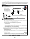
CONNECT MANIFOLD GAUGE SET AND WEIGH−IN
CHARGE
After the evacuation procedure, reconnect the manifold
gauge set as illustrated in figure 19.
NOTE − Temperature sensor illustrated in figure 19 is not
required for initial system weigh in charging.
1. Close manifold gauge set valves and connect the
gauge set as exampled in figure 19.
2. Check that fan rotates freely.