


Page 28
506728−01
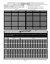
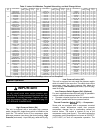
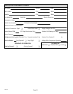
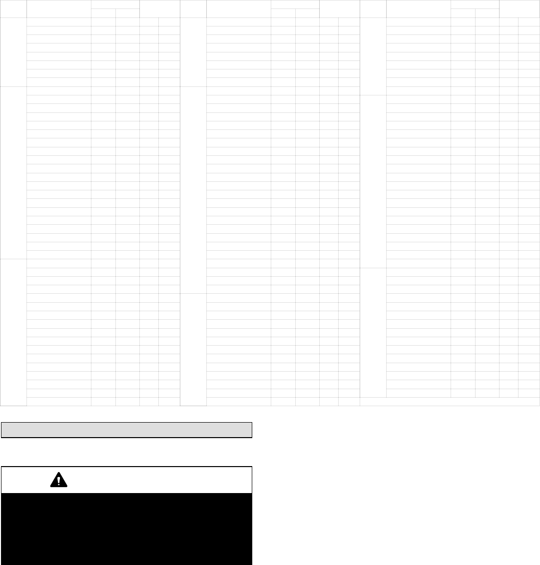
Table 5. Indoor Unit Matches, Targeted Subcooling, and Add Charge Values
OD
Size
Indoor Model #
Subcool
Additional
Charge
OD
Size
Indoor Model #
Subcool
Additional
Charge
OD
Size
Indoor Model #
Subcool
Additional
Charge
Heat Cool Heat Cool Heat Cool
−018
CBX27UH−018 13 14 1 9
−030
CH33−43C 4 9 1 12
−042
CH33−60D 12 8 0 9
CBX27UH−024 13 14 1 9 CR33−30, −36 22 5 1 0 CH33−62D 19 7 1 7
CBX32MV−018/024 12 14 0 0 CX34−31 17 15 2 10 CR33−50, −60 29 5 0 4
CH33−25A 14 14 0 7 CX34−36 25 6 0 10 CR33−60D 29 5 0 4
CH33−25B 14 13 0 5 CX34−38 14 17 2 10 CX34−49 11 6 1 4
CR33−30/36 12 5 0 7 CX34−42 25 6 0 10 CX34−50, −60 25 8 1 15
CX34−25 15 15 1 1 CX34−43 13 17 2 14 CX34−60 8 8 1 4
CX34−31 14 24 1 12 CX34−44, −48 9 21 2 12 CX34−62C 8 11 3 10
−024
CBX26UH−024 17 3 0 15
−036
CBX26UH−036 31 3 0 4 CX34−62D 11 7 1 15
CBX27UH−024 12 12 1 2 CBX27UH−036 18 3 0 5
−048
CBX26UH−048 20 10 3 11
CBX32M−018, −024 14 11 0 4 CBX27UH−042 11 4 0 1 CBX27UH−048 16 6 0 0
CBX32M−030 12 12 1 2 CBX27UH−048 11 4 0 1 CBX27UH−060 12 6 1 4
CBX32MV−018/024 14 11 0 4 CBX32M−036 18 3 0 5 CBX32M−048 16 6 0 0
CBX32MV−024/030 12 12 1 2 CBX32M−042 18 3 0 5 CBX32M−060 20 8 1 0
CBX32MV−036 11 11 2 1 CBX32MV−036 18 3 0 5 CBX32MV−048 16 6 0 0
CBX40UHV−024 11 11 2 1 CBX32MV−048 11 4 0 1 CBX32MV−060 20 8 1 0
CBX40UHV−030 11 11 2 1 CBX40UHV−042 11 4 0 1 CBX32MV−068 10 8 4 5
CH23−41 10 3 0 0 CBX40UHV−048 11 4 0 1 CBX40UHV−048 16 6 0 0
CH33−25A 20 10 1 1 CBX40UHV−036 18 3 0 5 CBX40UHV−060 20 8 1 0
CH33−25B 19 8 1 2 CH33−43B 14 8 2 1 CH23−68 24 6 2 8
CH33−31A 15 11 1 15 CH33−43C 26 9 2 10 CH33−50, −60C 17 6 1 5
CH33−36C 10 12 0 0 CH33−44/48B 24 8 2 3 CH33−60D 18 6 0 13
CH33−36A 20 10 1 1 CH33−48C 26 9 2 10 CH33−62D 13 7 3 6
CR33−30, −036 17 4 0 14 CH33−49C 15 8 2 12 CR33−50/60 19 6 1 1
CX34−25 15 9 0 15 CH33−50/60C 15 8 2 12 CR33−60 19 6 1 1
CX34−31 15 16 0 9 CR33−48 38 5 0 0 CX34−49C 10 6 1 9
CX34−36 26 6 0 9 CR33−50, −60 15 5 1 4 CX34−60 28 7 3 14
CX34−38 13 11 1 7 CX34−38 40 4 0 15 CX34−62C 10 6 3 12
−030
CBX26UH−030 19 11 1 5 CX34−43 23 8 2 8 CX34−62D 14 7 3 12
CBX27UH−030 10 2 2 15 CX34−44/48 40 4 0 15
−060
CBX26UH−060 31 6 3 0
CBX27UH−036 10 2 2 15 CX34−49 11 7 3 9 CBX27UH−060 13 7 0 8
CBX32M−030 15 4 2 7 CX34−50/60 23 8 2 8 CBX32M−060 17 5 1 4
CBX32M−036 10 2 2 15
−042
CBX26UH−042 42 5 0 8 CBX32MV−048 20 6 0 0
CBX32MV−024, −030 15 4 2 7 CBX27UH−042 13 5 2 2 CBX32MV−060 17 5 1 4
CBX32MV−036 10 2 2 15 CBX32M−048 13 5 2 2 CBX32MV−068 11 8 2 12
CBX40UHV−030 10 2 2 15 CBX32MV−048 13 5 2 2 CBX40UHV−048 20 6 0 0
CBX40UHV−036 10 2 2 15 CBX40UHV−042 13 5 2 2 CBX40UHV−060 17 5 1 4
CH23−41 11 4 0 8 CBX40UHV−048 13 5 2 2 CH23−68 27 7 0 13
CH23−51 11 6 0 14 CH23−68 20 9 1 5 CH33−50, −60C 11 4 0 0
CH33−31A 16 18 2 8 CH33−43B 7 9 3 2 CH33−62D 19 6 2 4
CH33−31B 16 18 2 6 CH33−43C 22 5 1 0 CR33−50/60 19 6 2 4
CH33−36A 10 6 0 6 CH33−44/48B 18 4 0 0 CR33−60 23 6 1 3
CH33−36B 6 3 0 0 CH33−48C 22 5 1 0 CX34−62C 10 7 2 14
CH33−36C 10 11 1 5 CH33−49C 16 6 1 6 CX34−62D 19 7 3 2
CH33−42B 16 18 2 6 CH33−50, −60C 10 9 3 4
*Amount of charge required in additional to charge shown on unit nameplate.
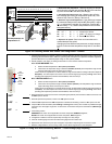
System Operation
IMPORTANT
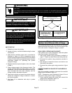
Some scroll compressor have internal vacuum protector
that will unload scrolls when suction pressure goes
below 20 psig. A hissing sound will be heard when the
compressor is running unloaded. Protector will reset
when low pressure in system is raised above 40 psig. DO
NOT REPLACE COMPRESSOR.
High Pressure Switch (S4)
This unit is equipped with a auto-reset high pressure
switch (single−pole, single−throw) which is located on the
liquid line. The switch shuts off the compressor when
discharge pressure rises above the factory setting. High
Pressure (auto reset) − trip at 590 psig, reset at 418 psig.
Low Pressure Switch (S87)
This unit is equipped an auto−reset low pressure switch
which is located on the vapor line. The switch shuts off the
compressor when the vapor pressure falls below the
factory setting. Low Pressure (auto reset) − trip at 25 psig,
reset at 40 psig.
Low Pressure Switch Bypass (S41) (Optional)
For use in applications where the heat pump is operated in
outdoor ambient temperatures below 15°F.
S Prevents nuisance trips form the low pressure switch
S Wired in parallel with the low pressure switch
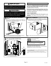
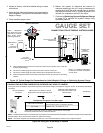
Thermal Protection Switch (S173) Ċ Compressor
Mounted
Some units are equipped with a compressor mounted
normally closed temperature switch that prevents
compressor damage due to overheating caused by
internal friction. The switch is located on top of the
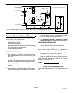
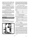
compressor casing (see figure 1). This switch senses the
compressor casing temperature and opens at 239−257°F
(115°C−125°C) to shut off compressor operation. The