


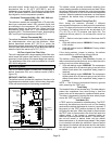
Page 25
XP14 SERIES
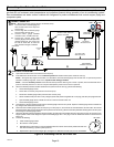
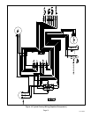
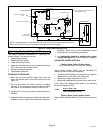
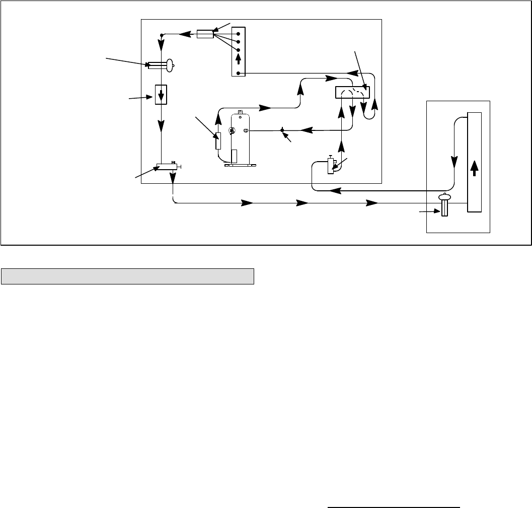
NOTE − Use gauge ports on vapor line valve and liquid valve for evacuating refrigerant lines and
indoor coil. Use true suction port to measure vapor pressure during charging.
OUTDOOR
COIL
CHECK / EXPANSION
VALVE
BI−FLOW FILTER / DRIER
COMPRESSOR
REVERSING VALVE
MUFFLER
NOTE − ARROWS INDICATE DIRECTION
OF REFRIGERANT FLOW
SERVICE
PORT
VAPOR
CHECK / EXPANSION VALVE
INDOOR UNIT
OUTDOOR UNIT
LIQUID LINE
SERVICE PORT
DISTRIBUTOR
INDOOR
COIL
TRUE SUCTION
PORT
Figure 21. Heat Pump Cooling Cycle
Optimizing System Refrigerant Charge
This section provides instructions on optimizing the
system charge. This section includes:
S Optimizing procedure
S Adjusting indoor airflow
S Using subcooling method
S Approved matched components, targeted subcooling
(SC) values and add charge values
S Normal operating pressures
S Temperature pressures
OPTIMIZING PROCEDURE
1. Move the low−side manifold gauge hose from the
vapor line service valve to the true suction port (see
figure 19).
2. Set the thermostat for either cooling or heating
demand. Turn on power to the indoor unit and close
the outdoor unit disconnect switch to start the unit.
3. Allow unit to run for five minutes to allow pressures to
stabilize.
4. Check the airflow as instructed under Adjusting Indoor
Airflow to verify or adjust indoor airflow for maximum
efficiency. Make any air flow adjustments before
continuing with the optimizing procedure.
5. Use subcooling method to optimize the system
charge (see figure 23). Adjust charge as necessary.
ADJUSTING INDOOR AIRFLOW
Heating Mode Indoor Airflow Check
(Only use when indoor unit has electric heat)
Indoor blower airflow (CFM) may be calculated by
energizing electric heat and measuring:
S Temperature rise between the return air and supply air
temperatures at the indoor coil blower unit,
S Measuring voltage supplied to the unit,
S Measuring amperage being drawn by the heat unit(s).
Then, apply the measurements taken in the following
formula to determine CFM:
CFM =
Amps x Volts x 3.41
1.08 x Temperature rise (F)
Cooling Mode Indoor Airflow Check
Check airflow using the Delta−T (DT) process using figure
22.