


Page 26
506728−01
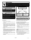
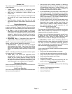
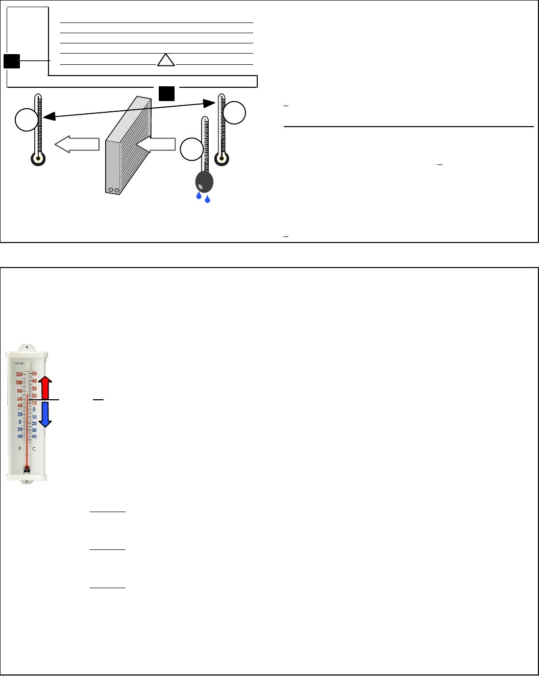
1. Determine the desired DTĊMeasure entering air temper-
ature using dry bulb (A) and wet bulb (B). DT is the intersect-
ing value of A and B in the table (see triangle).
2. Find temperature drop across coilĊMeasure the coil’s dry
bulb entering and leaving air temperatures (A and C). Tem-
perature Drop Formula: (T
Drop
) = A minus C.
3. Determine if fan needs adjustmentĊIf the difference between
the measured T
Drop
and the desired DT (T
Drop
–DT) is within
+
3º, no adjustment is needed. See examples: Assume DT =
15 and A temp. = 72º, these C temperatures would necessi-
tate stated actions:
Cº T
Drop
– DT = ºF ACTION
53º 19 – 15 = 4 Increase the airflow
58º 14 – 15 = −1 (within +3º range) no change
62º 10 – 15 = −5 Decrease the airflow
4. Adjust the fan speedĊSee indoor unit instructions to in-
crease/decrease fan speed.
Changing air flow affects all temperatures; recheck tempera-
tures to confirm that the temperature drop and DT are within
+
3º.
DT
80 24 24 24 23 23 22 22 22 20 19 18 17 16 15
78 23 23 23 22 22 21 21 20 19 18 17 16 15 14
76 22 22 22 21 21 20 19 19 18 17 16 15 14 13
74 21 21 21 20 19 19 18 17 16 16 15 14 13 12
72 20 20 19 18 17 17 16 15 15 14 13 12 11 10
70 19 19 18 18 17 17 16 15 15 14 13 12 11 10
57 58 59 60 61 62 63 64 65 66 67 68 69 70
Temp.
of air
entering
indoor
coil ºF
INDOOR
COIL
DRY
BULB
DRY
BULB
WET
BULB
B
T
Drop
19º
A
Dry−bulb
Wet−bulb ºF
A
72º
B
64º
C
53º
air flowair flow
All temperatures are
expressed in ºF
Figure 22. Checking Airflow over Indoor Coil Using Delta−T Formula
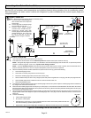
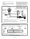
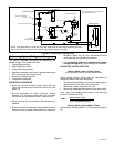
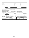
1. Check liquid and vapor line pressures. Compare pressures with either second−stage heat or cooling mode normal
operating pressures listed in table 4. Table 4 is a general guide and expect minor pressures variations. Significant
pressure differences may indicate improper charge or other system problem.
2. Decide whether to use cooling or heating mode based on current outdoor ambient temperature:
AUse COOLING MODE when:
S Outdoor ambient temperature is 60°F (15.5°C) and above.
S Indoor return air temperature range is between 70 to 80°F (21−27°C). This temperature range is what
the target subcooling values are base upon in table 5.
If indoor return air temperature is not within reference range, set thermostat to cooling mode and a setpoint of
68ºF (20ºC). This should place the outdoor unit into second−stage (high−capacity) cooling mode. When
operating and temperature pressures have stabilized, continue to step 3.
BUse HEATING MODE when:
S Outdoor ambient temperature is 59°F (15.0°C) and below.
S Indoor return air temperature range is between 65−75°F (18−24°C). This temperature range is what the
target subcooling values are base upon in table 5.
If indoor return air temperature is not within reference range, set thermostat to heating mode and a setpoint of
77ºF (25ºC). This should place the outdoor unit into second−stage (high−capacity) heating mode. When
operating and temperature pressures have stabilized, continue to step 3.
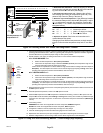
3. Read the liquid line pressure; then find its corresponding temperature pressure listed in table 3 and record it in
the SATº space to the left.
4. Read the liquid line temperature; record in the LIQº space to the left.
5. Subtract LIQº temperature from SATº temperature to determine subcooling; record it in SCº space to the left.
6. Compare SCº results with table 5 (either Heating or Cooling mode column), also consider any additional charge
required for line set lengths longer than 15 feet and/or unit matched component combinations (Add Charge
column).
7. If subcooling value is:
AGREATER than shown for the applicable unit match component, REMOVE refrigerant;
BLESS than shown for the applicable unit match component, ADD refrigerant.
8. If refrigerant is added or removed, repeat steps 3 through 6 to verify charge.
9. Close all manifold gauge set valves and disconnect gauge set from outdoor unit.
10. Replace the stem and service port caps and tighten as specified in Operating Service Valves on page .
11. Recheck voltage while the unit is running. Power must be within range shown on the nameplate.
USE
COOLING
MODE
USE
HEATING
MODE
60ºF
(15ºC)
SATº
LIQº –
SCº =
Figure 23. Using HFC−410A Subcooling Method Ċ Second Stage (High Capacity)