


6
NOTE: DIAGRAMS & ILLUSTRATIONS NOT TO SCALE.
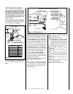
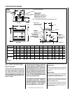
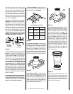
Figure 7
Right Side
Front Corner of
Fireplace Framing
6-1/2"
(152 mm)
3"
(76 mm)
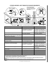
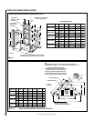
Step 1. FRAMING
Frame these appliances as illustrated in
Figure
9 on page 8,
unless the appliance is to be
installed in a corner
.
See
Figure 10 on page 8
for corner framing installations. All framing
details must allow for a minimum clearance to
combustible framing members as shown in
Table 2
.
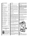
Step 2. ROUTING GAS LINE
Route a 1/2" (13 mm) gas line along the inside
of the right side framing as shown in
Figure 7
.
Gas lines must be routed, constructed and
made of materials that are in strict accordance
with local codes and regulations. All appli-
ances are factory-equipped with a flexible gas
line connector and 1/2 inch shutoff valve. (See
step 6 on page 23).
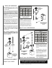
DETAILED INSTALLATION STEPS
The appliance is shipped with all gas controls
and components installed and pre-wired. Re-
move the shipping carton, exposing the front
glass door. Remove the top panel. Remove
the cardboard from underneath the pressure
relief plates. Press in simultaneously the left
and right side of the bottom hinged panel, to
release it. Lower the bottom hinged panel.
Open the two latches (located under the fire-
box floor) securing the glass door. Remove
the door by tilting it outward at the bottom and
lifting it up. Set the door aside protecting it
from inadvertent damage.
See Figure 53 on
page 24.
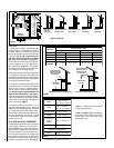
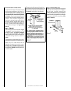
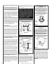
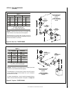
The fireplace should be secured to the side fram-
ing members using the unit's nailing flanges - one
top and bottom on each side of the fireplace front.
See
Figure 6.
Use 8d nails or their equivalent.
If the appliance is to be elevated above floor level,
a solid continuous platform must be constructed.
Headers may be in direct contact with the
appliance top spacers but must not be sup-
ported by them or notched to fit around them.
All construction above the appliance must be
self supporting. DO NOT use the appliance for
structural support.
Figure 6
Note: The nailing flanges, combustible members
and screw heads located in areas directly adjacent
to the nailing flanges, are EXEMPT from the 1/2”
clearance to combustible requirements for the
firebox outer wrapper. Combustible framing may be
in
direct contact with the nailing flanges and may
be located closer than 1/2” from screw heads and
the firebox wrapper in areas adjacent to the nailing
flanges. Frame the opening to the exact dimensions
specified in the framing details of this manual.
Side
Framing
Unit Nailing Flange
(No clearance to
combustible
framing is required)
Left Side Front Corner of Fireplace Shown
(Right Side Requirements the Same)
Unit Being Secured By Its Nailing Flanges
To The Framing