


4
NOTE: DIAGRAMS & ILLUSTRATIONS NOT TO SCALE.
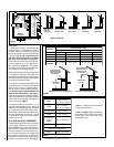
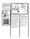
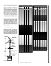
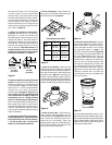
Shelf Above Fireplace With Rear Venting
Do not insulate the
space between the
appliance and the
area above it.
Shelf Height
(
see table)
Shelf Height
(
see table)
Do not insulate the
space between the
appliance and the
area above it.
Shelf Above Fireplace With Top Venting
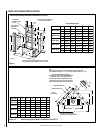
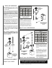
.oNledoM
)mm(sehcnithgieHflehS
woblEeergeD09enOhtiw-tneVpoTkcaBehttuOthgiartS-tneVraeR
tneVeruceSxelFeruceStneVeruceSxelFeruceS
8233-TDPM 2/144)0311(4/164)5711(A/NA/N
8233-RDPM A/NA/N4/133)548(4/133)548(
0353-DPM 2/164)1811(4/184)6221(34/15)598(34/15)598(
5304-DPM
0454-DPM
2/115)8031(4/135)3531(4/104)2201(4/104)2201(
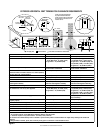
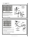
KCAB
)mm31(.ni2/1
srecaps)mm0(.ni0
SEDIS
**)mm31(.ni2/1
srecaps)mm0(.ni0
SRECAPSPOT)mm0(.ni0
ROOLF)mm0(.ni0
mottoBmorF
ottinUfo
gnilieC
)mm6261(.ni46
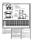
TNEV*)mm4.52(.ni1
SECNARAELCECIVRES
TNORF)sretem9.0(.teeF3
(Rear Vent Application
HORIZONTAL VENT
without a chase)
HORIZONTAL VENT
(Rear Vent Application
With a chase)
HORIZONTAL VENT
(Top Vent
Application)
VERTICAL VENT
(Top Vent
Application)
(Rear Vent
VERTICAL VENT
Application)
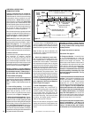
APPLICATION
REAR VENT
APPLICATION
TOP VENT
APPLICATION
TOP VENT
REAR VENT
APPLICATION
TOP VENT
APPLICATION
RECESSED
INSTALLATION
TOP VENT
APPLICATION
APPLICATION
TOP VENT
APPLICATION
TOP VENT
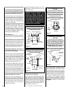
Figure 2
Figure 3
*Note: 3 in. (75 mm) above any horizontal/
inclined vent component.
**Note: See page 5, step 1 for clearance
requirements to the nailing flange located
at each side of the unit and any screw
heads adjacent to it.
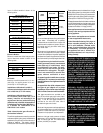
Table 2
APPLIANCE AND VENT CLEARANCES
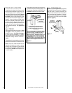
The appliance is approved with zero clearance
to combustible materials on all sides (as de-
tailed in
Table 2 )
, with the following exception:
When the unit is installed with one side flush
with a wall, the wall on the other side of the unit
must not extend beyond the front edge of the
unit. In addition, when the unit is recessed, the
side walls surrounding the unit must not extend
beyond the front edge of the unit. See
Figure 2
.
Typical Locations
The appliance should be mounted on a fully
supported base extending the full width and
depth of the unit. The appliance may be located
on or near conventional construction materi-
als. However, if installed on combustible mate-
rials, such as carpeting, vinyl tile, etc., a metal
or wood barrier covering the entire bottom
surface must be used.
LOCATION
In selecting the location, the aesthetic and
functional use of the appliance are primary
concerns. However, vent system routing to the
exterior and access to the fuel supply are also
important. Due to high temperatures the
appliance should be located out of traffic
and away from furniture and draperies.
Consideration should be given to traffic ways,
furniture, draperies, etc., due to elevated sur-
face temperatures (
Figure 2
). The location
should also be free of electrical, plumbing or
other heating/air conditioning ducting.
These direct vent appliances are uniquely suited
for installations requiring a utility shelf posi-
tioned directly above the fireplace. Utility shelves
like these are commonly used for locating tele-
vision sets and decorative plants.
To provide for the lowest possible shelf surface
use the alternate rear vent outlet with attached
venting routed in a way to minimize obstruc-
tions to the use of the space above the appli-
ance. Do not insulate the space between the
appliance and the area above it. See
Figure 3
.
The minimum height from the base of the appli-
ance to the underside of combustible materials
used to construct a utility shelf in this fashion is
shown in the table in
Figure 3
.