


5
NOTE: DIAGRAMS & ILLUSTRATIONS NOT TO SCALE.
hctiPfooR
H
)teef(
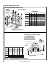
21/6ottalF0.1
21/7ot21/6revO52.1
21/8ot21/7revO5.1
21/9ot21/8revO0.2
21/01ot21/9revO5.2
21/11ot21/01revO52.3
21/21ot21/11revO0.4
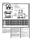
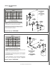
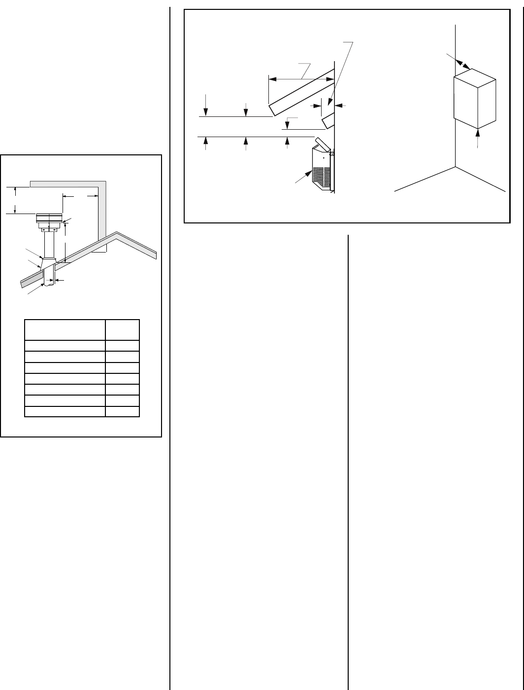
Figure 4
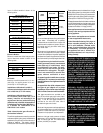
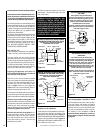
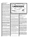
Figure 5 -
Side Elevation View
3"
(76 mm)
12"
(305 mm)
Termination Kit
Combustible Projection
greater than inches in length
Combustible Projection
2-1/2 inches or less in length
18"
(457 mm)
Ventilated
Soffit
Unventilated
Soffit
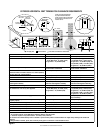
Horizontal Vent Termination Clearances
2-1/2
Termination Kit
All horizontal terminations
may be located as close
as 6” (152mm) to any
(non-combustible and
combustible) exterior
sidewall. This distance
may be decreased to
2” (51mm) for non-
combustible exterior
sidewalls only, if the
SV4.5HT-2 termination
is used.
Horizontal Vent Termination Clearances
The horizontal vent termination must have a
minimum of 3" (76 mm) clearance to any over-
head combustible projection of 2-1/2" (64 mm)
or less. See
Figure 5.
For projections exceed-
ing 2-1/2" (64 mm), see
Figure 5
. All horizontal
terminations may be located as close as 6"
(152mm) to any (non-combustible and com-
bustible) exterior sidewall. This distance may
be decreased to 2" (51mm) for non-combus-
tible exterior sidewalls only, if the SV4.5HT-2
termination is used. For additional vent location
restrictions refer to
Figure 8 on page 7
.
Terminate multiple vent terminations accord-
ing to the installation codes listed on this
page.
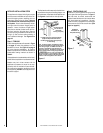
Vertical Vent Termination Clearances
VENT TERMINATION CLEARANCES
These instructions should be used as a guide-
line and do not supersede local codes in any
way. Install vent according to local codes,
these instructions, the current National Fuel
Gas Code (ANSI-Z223.1) in the USA or the
current standards of CAN/CGA-B149.1 and -
B149.2 in Canada.
Terminate single vent caps relative to building
components according to
Figure 4
.
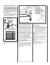
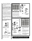
Step 3. (page 9) Install the vent system and
exterior termination.
Step 4. (page 22) Field Wiring
a. Millivolt Appliances – Install the operating
control switch (not factory provided) and
bring in electrical service line for forced air
circulating blower (optional equipment).
b. Electronic Appliances – Field wire and
install operating control switch.
Step 5. (page 22) Install blower kit (optional
equipment).
Step 6. (page 23) Make connection to gas
supply.
Step 7. (page 24) Install the logs, decora-
tive volcanic stone and glowing embers.
Step 8. (page 24) Checkout appliance op-
eration.
Step 9. (page 24) Install glass door frame
assembly.
Step 10. (page 25) Adjust burner to ensure
proper flame appearance.
Step 11. (page 25) Install the hoods.
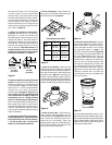
TYPICAL INSTALLATION SEQUENCE
The typical sequence of installation follows,
however, each installation is unique resulting in
variations to those described.
See the page numbers references in the follow-
ing steps for detailed procedures.
Step 1. (page 6) Construct the appliance
framing. Position the appliance within the
framing and secure with nailing brackets.
Step 2. (page 6) Route gas supply line to
appliance location.
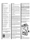
12
X
Roof Pitch is X/12
2 FT
MIN.
2 FT MIN.
Lowest
Discharge
Opening
H*
*H = MINIMUM HEIGHT FROM ROOF TO
LOWEST DISCHARGE OPENING OF VENT
TERMINATION HEIGHTS FOR VENTS ABOVE
FLAT OR SLOPED ROOFS
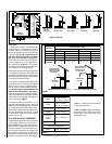
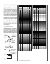
Horizontal Overhang
Vertical
Wall
Vent
Termination
Storm Collar
Concentric
Vent Pipe
Flashing
1 inch (25.4 mm) Minimum
Clearance to Combustibles