


18
NOTE: DIAGRAMS & ILLUSTRATIONS NOT TO SCALE.
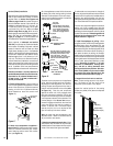
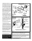
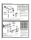
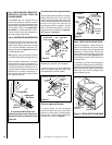
Note: See Figure 33 for wall thickness range reductions when using SV4.5HT-2.
H
H = 28 in. (711 mm) Maximum.
7 in. (178 mm)
*When using Secure Flex,
use Firestop/Spacer
SF4.5HF
*Wall Firestop/Spacer
(SV4.5HF)
H
V
*Wall Firestop/Spacer
(SV4.5HF)
*When using Secure Flex,
use Firestop/Spacer
SF4.5VF
*Ceiling
Firestop/Spacer
(SV4.5VF)
*When using Secure Flex,
use Firestop/Spacer
SF4.5HF
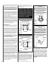
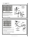
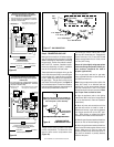
Figure 35
-
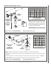
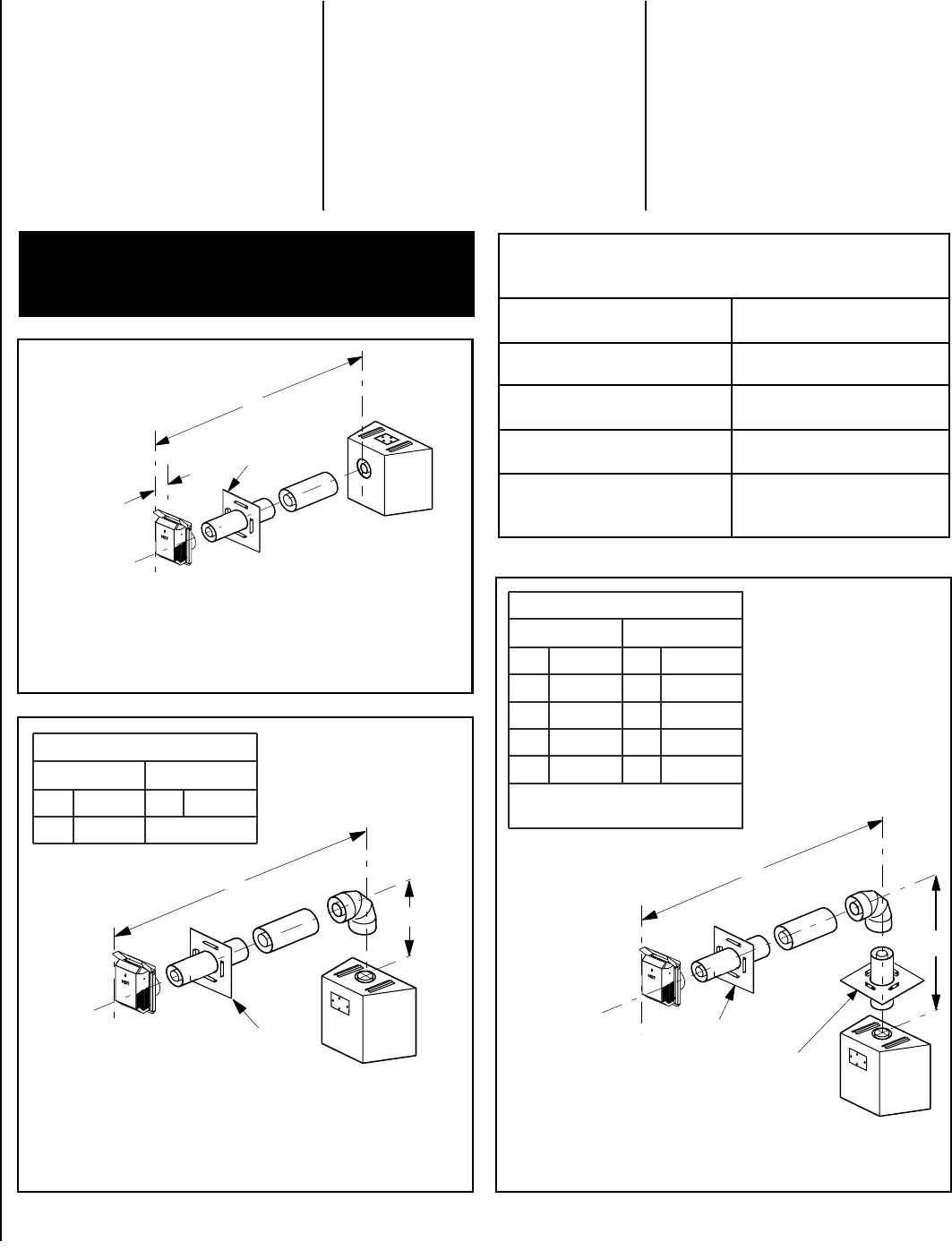
Top Vent -
ONE 90 DEGREE ELBOW - ELBOW CONNECTION AT APPLIANCE
Figure 36
-
Top Vent - ONE 90 DEGREE ELBOW -
ELBOW CONNECTION NOT DIRECTLY AT APPLIANCE
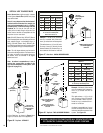
Figure 34
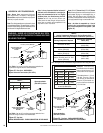
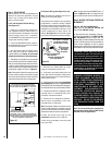
- Rear Vent - NO ELBOWS -
Square Horizontal Termination (SV4.5HT-2)
See
Table 4
as an aid in venting component selection for a
particular range of exterior wall thicknesses.
H
*Wall
Firestop/Spacer
(SV4.5HF)
V
*When using Secure Flex,
use Firestop/Spacer
SF4.5HF
HORIZONTAL VENT FIGURES/TABLES
Note: SV4.5VF (Secure Vent), SF4.5VF (Secure
Flex) firestop/spacer must be used anytime vent
pipe passes through a combustible floor or
ceiling. SV4.5HF (Secure Vent), SF4.5HF (Se-
cure Flex) firestop/spacer must be used anytime
vent pipe passes through a combustible wall.
Square termination
(SV4.5HT-2) shown.
Square termination
(SV4.5HT-2) shown.
See
Table 4
as an aid in venting component selection for
a particular range of exterior wall thicknesses.
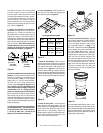
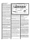
Note: It is very important that the horizontal/
inclined run be maintained in a straight (no
dips) and recommended to be in a slightly
elevated plane, in a direction away from the
fireplace of 1/4" rise per foot (20 mm per
meter) which is ideal, though rise per foot run
ratios that are smaller are acceptable all the
way down to at or near level.
Note: Secure Vent components (rigid vent
pipe and terminal) are shown in the figures;
Secure Flex components (flexible vent pipe and
terminal) may also be used.
Note: Two 45 degree elbows may be used in place
of one 90 degree elbow. The same rise to run ratios,
as shown in the venting figures for 90 elbows,must
be followed if 45 degree elbows are used.
WARNING: UNDER NO CIRCUMSTANCES MAY SEPA-
RATE SECTIONS OF CONCENTRIC FLEXIBLE VENT PIPE
BE JOINED TOGETHER.
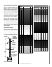
4ELBAT
llaWroiretxEsuoiraVrofderiuqeRstnenopmoCgnitneV
)2-TH5.4VS(noitanimreTerauqSehTgnisUnehW,sessenkcihT
deriuqeRstnenopmoCgnitneV
ssenkcihTllaWroiretxE
)mm(sehcni
ylnOtiKnoitanimreT
4/1-9ot6
)532ot251(
tnev.ni6dnatiKnoitanimreT
)6L5.4VS(noitces
4/3-0141ot
)653ot372(
tnev.ni21dnatiKnoitanimreT
)21L5.4VS(noitces
02ot4/3-61
)805ot624(
cipocseleTdnatiKnoitanimreT
tnev.ni6dna)AL5.4VS(noitces
)6L5.4VS(noitces
02ot4/3-11
)805ot992(
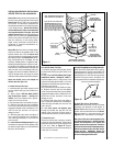
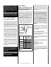
H Maximum
V Minimum
feet feet
5
(1.524)
1 (0.305)
10 (3.048) 2 (0.610)
15 (4.572) 3 (0.914)
20 (6.096) 4 (1.219)
V + H = 40 feet (12.2 m) Max.
H = 20 ft. (6.096 m) Max.
TABLE G
(meters)
(meters)
TABLE F
H Maximum V Minimum
feet
feet
3
(0.914)
Elbow Only
(meters)
(meters)
Note: An elbow is acceptable as 1 foot of
vertical rise, except where an elbow is the
only vertical component in the system. (See
Figure 35 ).
Example: If 20 feet of (H)
horizontal vent run is needed,
then 4 feet minimum of (V)
vertical vent will be required.
This table shows a 1 (V) to 5
(H) ratio. For every 1 foot of
(V) vertical, you are allowed
5 feet of (H) horizontal run,
up to a maximum horizontal
run of 20 feet.