


10
NOTE: DIAGRAMS & ILLUSTRATIONS NOT TO SCALE.
VENT SEAL PLATE
GASKET
FIREBOX TOP
CABINET TOP
SECURING
SCREWS
VENT
COVER PLATE
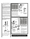
TOP VENT
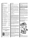
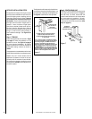
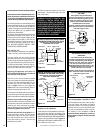
ON MPD-3530/4035/4540 SERIES MODELS
(COMBINED TOP AND REAR VENT UNITS)
TOP VENT SEAL & COVER PLATE REMOVAL
WHEN USING THE TOP VENT
COVER PLATE
SECURING SCREWS
CROSS SECTION
(INSIDE UNIT)
(OUTSIDE UNIT)
VENT SEAL PLATE
GASKET
SECURING
SCREWS
CROSS SECTION
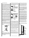
LINTEL
SECURING
SCREWS
LINTEL
REAR VENT
COVER PLATE
SECURING SCREWS
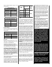
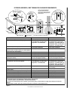
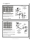
ON MPD-3530/4035/4540 SERIES MODELS
(COMBINED TOP AND REAR VENT UNITS)
REAR VENT SEAL & COVER PLATE REMOVAL
WHEN USING THE REAR VENT
CABINET BACK
(INSIDE UNIT)
(OUTSIDE UNIT)
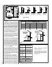
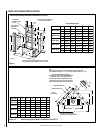
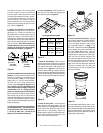
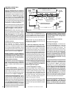
A vent restrictor may be needed when
vertically terminating the vent system above
the roof (when using the appliance top vent),
install vent restrictor in the top vent of the
fireplace outlet on MPD-3530/4035/4540
and MPDT-3328 series models.
RESTRICTOR
APPLIANCE TOP
VENT OUTLET
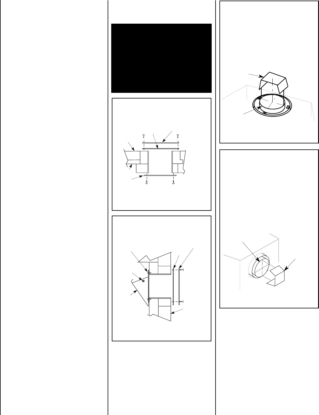
VENT RESTRICTOR INSTALLATION
(TOP VENT)
If needed, install the restrictor orientated as
shown, either from inside or outside the unit,
in the inner fireplace collar.
INNER
FIREPLACE
COLLAR
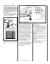
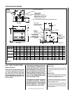
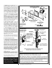
RESTRICTOR
APPLIANCE REAR
VENT OUTLET
A vent restrictor may be needed when
horzontally terminating the vent system from
the rear of the appliance (when using the
appliance rear vent), install vent restrictor in
the rear vent of the fireplace outlet on
MPD-3530/4035/4540 series models, in any
installation that has a vertical vent run in
excess of three feet (0.914 meters).
VENT RESTRICTOR INSTALLATION
(REAR VENT)
INNER FIREPLACE
COLLAR
If needed, install the restrictor orientated as
shown, either from inside or outside the unit,
in the inner fireplace collar.
Figure 12
Figure 14
Figure 15
Figure 13
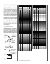
Select Venting System - Horizontal or Vertical
With the appliance secured in framing, deter-
mine vent routing and identify the exterior
termination location. The following sections
describe vertical (roof) and horizontal (exte-
rior wall) vent applications. Refer to the sec-
tion relating to your installation. A list of
approved venting components is shown in
the two tables on page 27 and the two tables
on page 28.
Installation of Vent Restrictor
A vent restrictor may be needed with this appli-
ance, install vent restrictor (provided) in the
appliance top flue outlet as shown in
Figure 14
(MPDT-3328, MPD-3530, MPD-4035 and MPD-
4540)
or rear flue outlet as shown in
Figure 15
(MPD-3530, MPD-4035 and MPD-4540)
. It is
held in place by friction, only.
WARNING: FAILURE TO REINSTALL AND
SECURELY TIGHTEN COVER PLATE
SCREWS COULD RESULT IN LEAKAGE OF
FLUE PRODUCTS INTO THE LIVING SPACE.
VENT COVER PLATE AND VENT SEAL PLATE
MUST REMAIN SECURELY INSTALLED ON
UNUSED VENT COLLAR. FAILURE TO DO
SO COULD RESULT IN LEAKAGE OF FLUE
PRODUCTS INTO LIVING SPACE.
Massachusetts Horizontal Vent Requirements
In the Commonwealth of Massachusetts, hori-
zontal terminations installed less than seven
(7) feet above the finished grade must comply
with the following additional requirements:
• A hard wired carbon monoxide detector with
an alarm and battery back-up must be installed
on the floor level where the gas fireplace is
installed. The carbon monoxide detector must
comply with NFPA 720, be ANSI/UL 2034
listed and be ISA certified.
• A metal or plastic identification plate must be
permanently mounted to the exterior of the
building at a minimum height of eight (8) feet
above grade and be directly in line with the
horizontal termination. The sign must read, in
print size no less than one-half (1/2) inch in
size, GAS VENT DIRECTLY BELOW. KEEP
CLEAR OF ALL OBSTRUCTIONS.
New York City, NY:
These fireplaces are approved for installation
in New York City in the US state of New York.
The vent system may not service multiple
appliances, and must never be connected to a
flue serving a solid fuel burning appliance. The
vent pipe is tested to be run inside an enclos-
ing wall (such as a chase). There is no require-
ment for inspection openings in the enclosing
wall at any of the joints in the vent pipe.
Preparing the Appliance Vent Collar on
MPD-3530/4035/4540 Series (Combined
Top and Rear Vent) Models
Each of the unit's two vent collars are sealed
with a cover plate and a seal plate and gasket.
The cover, and seal plate and gasket must be
removed from the vent collar being used.
Refer to
Figure 12
for top vent usage and
Figure 13
for rear, and the following steps to
prepare the appropriate collar for use.
From the vent collar being used, remove the four
screws securing the vent seal plate and gasket.
Remove and discard the seal plate and gasket.
When the top vent collar is being used, from
inside the firebox, loosen the two screws in the
keyhole slots of the cover plate and remove the
remaining two cover plate securing screws.
Remove and discard the cover plate. Reinstall
and securely tighten all four screws.
When the rear vent collar is being used, from
inside the firebox, remove the two screws
securing the lintel to the rear wall of the fire-
box, then remove the lintel. Remove the four
cover plate securing screws. Remove and
discard the cover plate.
Reinstall and securely tighten all four cover
plate screws. Re-secure the lintel to the rear
wall of the firebox.