


23
NOTE: DIAGRAMS & ILLUSTRATIONS NOT TO SCALE.
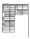
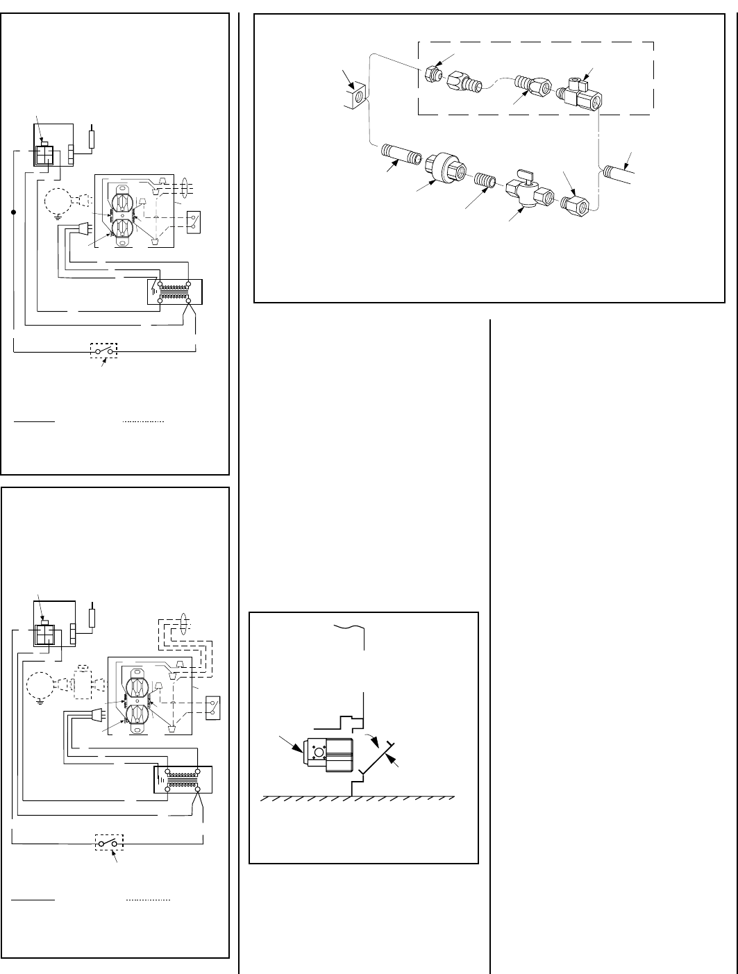
Gas
Stub
1/2" x
3/8" Flare
Shut-Off Valve
3/8" Flex Tubing
3/8" Nipple
3/8"
Union
3/8" Close Nipple
3/8" Shut-Off Valve
1/2" x 3/8"
Reducer
Gas
Valve
Gas Flex Line Connector
3/8" NPT x
3/8"
Flare Fitting
Control
Valve
Lower Control
Compartment
Door
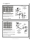
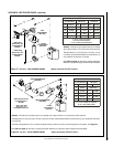
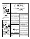
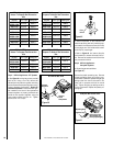
Open the lower panel or louver assembly by
pushing in simultaneously the left and right
side of the panel or louver assembly.
Figure 48
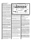
Figure 47 -
GAS CONNECTION
Figure 46
Figure 45
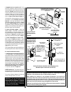
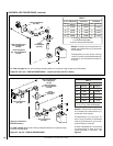
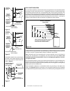
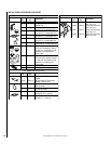
1. If any of the original wire as supplied must be replaced,
1. it must be replaced with Type AWM 105°C – 18 GA. wire.
2. 120V, 60Hz – Less than 3 amps.
BK
Transf.
120 V.
24 V
Factory Wired Field Wired
BL
Electronic Wiring Diagram (Honeywell)
Showing the Blower Wiring for the Optional
FBK-100 and FBK-200 Kits
R
W
BL
W
Gas Valve
B
R
IGNITER
BK
*Blower speed control switch is provided in FBK200 blower kit.
Schematic Representation Only
**ON/OFF Switch (Integral
with Gas Valve)
**Leave the ON/OFF switch, which is integral
with the gas valve, in the ON position.
OPTIONAL APPLIANCE-MOUNTED ON/OFF SWITCH
OR OPTIONAL WALL SWITCH
OR OPTIONAL THERMOSTAT
OR OPTIONAL REMOTE RECEIVER
G
OPT
BLOWER
PILOT
ASSEMBLY
Junction Box
White
Green
Red
Black
Neutral
Side of
Receptacle
Tab Intact
Green
Ground
Screw
Hot
Side of
Receptacle
Tab
Broken
120 VAC - Black
n
e
erG-dnuor
G
Optional
Accessory
Switch
e
ti
h
W
-
lar
t
u
e
N
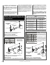
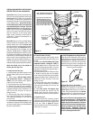
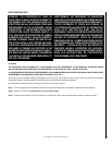
1. If any of the original wire as supplied must be replaced,
1. it must be replaced with Type AWM 105°C – 18 GA. wire.
2. 120V, 60Hz – Less than 3 amps.
BK
Transf.
120 V.
24 V
Factory Wired Field Wired
BL
Electronic Wiring Diagram (Honeywell)
Showing the Blower Wiring for the Optional
FBK-250 Kits
R
WH
BL
W
Gas Valve
B
R
IGNITER
BK
Schematic Representation Only
*ON/OFF Switch (Integral
with Gas Valve)
Optional
FBK-250
Module
*Leave the ON/OFF switch, which is integral
with the gas valve, in the ON position.
G
OPTIONAL APPLIANCE-MOUNTED ON/OFF SWITCH
OR OPTIONAL WALL SWITCH OR OPTIONAL THERMOSTAT
OR OPTIONAL REMOTE RECEIVER
PILOT
ASSEMBLY
OPT
BLOWER
Junction Box
White
Green
Red
Black
Neutral
Side of
Receptacle
Tab Intact
Green
Ground
Screw
Hot
Side of
Receptacle
Tab
Broken
Optional
Accessory
Switch
120 VAC - Black
n
e
erG-dnuor
G
e
ti
h
W
-
lar
t
u
e
N
OPENING CONTROL
COMPARTMENT DOOR
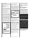
The millivolt control valve has a 3/8"
(10 mm) NPT thread inlet port. The electronic
control valve has a 1/2" (13 mm) NPT thread
inlet port and is fitted with a 1/2" x 3/8" (13 mm
x 10 mm) NPT fitting.
Secure all joints tightly using appropriate
tools and sealing compounds (ensure pro-
pane resistant compounds are used in
propane applications).
Turn on gas supply and test for gas leaks,
using a gas leak test solution (also referred to
as bubble leak solution).
Note: Using a soapy water solution (50% dish
soap, 50% water) is an effective leak test
solution but it is not recommended, because
the soap residue that is left on the pipes/
fittings can result in corrosion over time. Never
use an open flame to check for leaks.
A. Light the appliance (refer to the lighting
instructions label in the control compartment
or in the Homeowner's Care and Operation
Instructions).
B. Brush all joints and connections with the
gas leak test solution to check for leaks. If
bubbles are formed, or gas odor is detected,
turn the gas control knob to the “OFF” posi-
tion. Either tighten or refasten the leaking
connection and retest as described above.
C. When the gas lines are tested and leak free,
be sure to rinse off the leak testing solution.
D. When the gas lines are tested and leak free,
observe the individual tongues of flame on the
burner. Make sure all ports are open and
producing flame evenly across the burner. If
any ports are blocked, or partially blocked,
clean out the ports.
The gas control valve is located in the lower
control compartment. To access the valve
open the lower control compartment door
(Figure 48)
.
Make gas line connections. All codes require a
shut-off valve mounted in the supply line.
Fig-
ure 47
illustrates two methods for connecting
the gas supply. The flex-line method is accept-
able in the U.S., however, Canadian require-
ments vary depending on locality. Installation
must be in compliance with local codes.
These appliances are equipped with a gas flex
line for use (where permitted) in connecting the
unit to the gas line. A gas flex line is provided
to aid in attaching the direct vent appliance to
the gas supply. The gas flex line can only be
used where local codes permit. See
Figure 47
for flex line description. The flex line is rated for
both natural and propane gas. A manual shut off
valve is also provided with the flex line.
Step 6. CONNECTING GAS LINE