


22
NOTE: DIAGRAMS & ILLUSTRATIONS NOT TO SCALE.
WARNING: ELECTRONIC MODELS OF
THESE APPLIANCES ARE EQUIPPED
WITH A THREE-PRONG (GROUNDING)
PLUG UTILIZED IN CONNECTING THE
ELECTRONIC COMPONENTS TO THE
JUNCTION BOX IN THE LOWER COM-
PARTMENT. THIS GROUNDING PLUG
PROVIDES PROTECTION AGAINST
SHOCK HAZARD AND SHOULD BE
PLUGGED DIRECTLY INTO THE PROP-
ERLY GROUNDED THREE-PRONG RE-
CEPTACLE. DO NOT CUT OR REMOVE
THE GROUNDING PRONG FROM THE
PLUG.
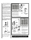
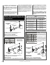
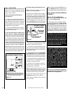
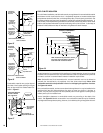
SIT And Honeywell Millivolt Wiring Diagram
If any of the original wire as supplied must be replaced,
it must be replaced with Type AWM105°C – 18 GA. wire.
Thermopile
TH
TP
TH
TP
*TWIST WIRES “A” AND “B” TOGETHER TO OPERATE UNIT
SOLELY BY MANIPULATING THE GAS VALVE CONTROL KNOB;
OR CONNECT WIRES TO OPTIONAL ON/OFF SWITCH OR WALL
SWITCH OR THERMOSTAT TO OPERATE UNIT.
*OPTIONAL ON/OFF SWITCH,
WALL SWITCH, THERMOSTAT
OR REMOTE CONTROL RECEIVER
AB
Figure 43
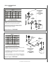
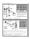
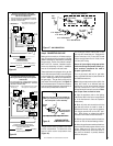
*Narrow (2-1/8 inch Wide)
J-Box Required
See Figure 11 on page 8
for Optional Electrical
Inlet Knockout Location
*Field-Provide
Junction Box
and Duplex
Receptacle
Optional J-Box/Outlet Box
(Left Side Shown)
Figure 44
Note: The tab connecting the receptacles of
the outlet box must be broken in FBK-100 and
FBK-200 blower kit applications.
Step 4. FIELD WIRING
Refer to Section A for millivolt appliances and
Section B for electronic appliances. The gas
valve is set in place and pre-wired at the
factory on both models.
1. Route a 3-wire 120Vac 60Hz 1ph power
supply to the appliance junction box.
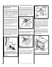
2. If the factory-provided outlet/junction box
at the right rear of the fireplace is being used,
remove the outlet box from the junction box by
removing two screws.
3. Connect the power supply wires (including the
ground supply wire) as shown in
Figures 45 or 46.
(If the field-provided J-box/outlet box is being used,
all of the outlet box wiring must be field-provided.)
4. Locate and install a low voltage (24V) wall-
mounted switch or thermostat (both field-
provided)in the desired location.
5. Connect the low voltage wire, located in-
side the control compartment, to the wall-
mounted switch or thermostat.
Note: The supplied 15 feet of 2 conductor wire has
one end of each conductor connected to the gas
valve circuit and the other end of each conductor
placed loose inside the control compartment.
6. Insert the control circuit plug into the
unswitched receptacle of the outlet box.
7. After wiring is complete, mount the outlet
box to the J-Box.
A. SIT and Honeywell Millivolt Wiring
(See Figure 43)
–
1. Select any of the following optional con-
trols: appliance-mounted (rocker switch) or
wall-mounted switch, thermostat, or one of the
optional remote control kits. If appliance-
mounted ON/OFF control is selected mount it in
the gas valve mounting bracket.
2. If wall-mounted ON/OFF control or thermo-
stat is selected mount it in a convenient location
on a wall near the fireplace.
3. Wire the control within the millivolt control
circuit using the 15 feet of 2 conductor wire
supplied with the unit . Caution: do not connect
the optional wall switch to a 120V power supply.
4. Alternatively, the appliance may be operated
without the use of the controls indicated in step 1,
solely by manipulating the gas valve control knob.
In order to use this method, twist the free ends of
the two conductor wire (located inside the control
compartment) together as shown in
Figure 43
.
Note: The supplied 15 feet of 2 conductor wire has
one end of each conductor connected to the gas
valve circuit and the other end of each conductor
placed loose inside the control compartment.
Note: The gas valve-mounted ON/OFF switch is
shown in Figure 45 or 46. It is integral with the
gas valve and should be set to the ON position.
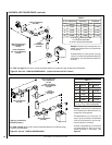
Step 5. WIRING - OPTIONAL FORCED AIR
BLOWER KIT
FBK-100, FBK-200 and FBK250 Kits
(See Figure 45 for FBK-100, FBK-200 and
Figure 46 for FBK-250 wiring)
-
An electrical outlet box (receptacle) is factory -
provided for the installation of the FBK-100, FBK-
200 and FBK-250 forced air blower kits. (An
optional field-provided outletbox/J-Box may also
be used. Electrical power must be connected to
either of these receptacles in order to operate
these blowers. Install the blower kits according to
the installation instructions provided with the kits.
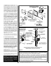
B. Electronic Wiring
(See Figure 45 or 46)
–
Note: The electronic appliance must be con-
nected to the main power supply.
The junction box is located on the right side of
the appliance. It contains a factory installed
and wired outlet box (duplex receptacle). Also,
an optional field-provided junction box with
receptacle may be installed at the front of the
control compartment on either side of the
cabinet.
See Figure 44.
It will be held in place
by a conduit fitting and locknut (field-provided).
IMPORTANT: Ground supply wire must be
connected to the green wire attached to the
outlet receptacle's green ground screw. See
Figure 45 or 46
. Failure to do so will result in
a potential safety hazard. The appliance must
be electrically grounded in accordance with
local codes or, in the absence of local codes,
the National Electrical Code, ANSI/NFPA 70-
(latest edition). (In Canada, the current CSA
C22-1 Canadian Electrical Code.)