


24
NOTE: DIAGRAMS & ILLUSTRATIONS NOT TO SCALE.
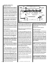
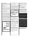
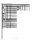
ELECTRONIC
Proper Flame
Adjustment
Pilot
Nozzle
3/8 To 1/2 Inch
(9 mm to 13 mm)
Ground
Electrode
Flame Rod
Hot Surface
Igniter
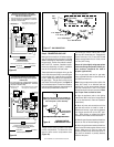
Latch
Latch
Glass Door
Firebox Floor
Bottom Vee-flange
Door Frame
Top Flange
Door Frame
Figure 52
Replace logs if removed for pilot inspection.
To light the burner; turn “ON” the remote wall
switch and rotate the gas valve control knob
counterclockwise to the “ON” position.
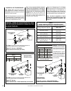
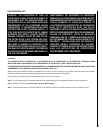
Figure 51
SIT MILLIVOLT
Thermocouple
Hood Ignitor Rod
3/8" Min
(9 mm)
Thermopile
Pilot
Nozzels
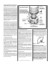
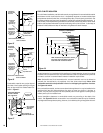
SIT and Honeywell Millivolt Appliance Checkout
The pilot flame should be steady, not lifting or
floating. Flame should be blue in color with
traces of orange at the outer edge. The top 3/8"
(10 mm) at the pilot generator (thermopile) and
the top 1/8" min (tip) of the quick drop out
thermocouple should be engulfed in the pilot
flame. The flame should project 1" (25 mm)
beyond the hood at all three ports (
Figure 50 -
SIT, Figure 51 - Honeywell
)
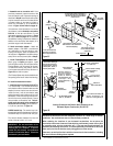
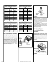
Figure 53
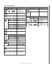
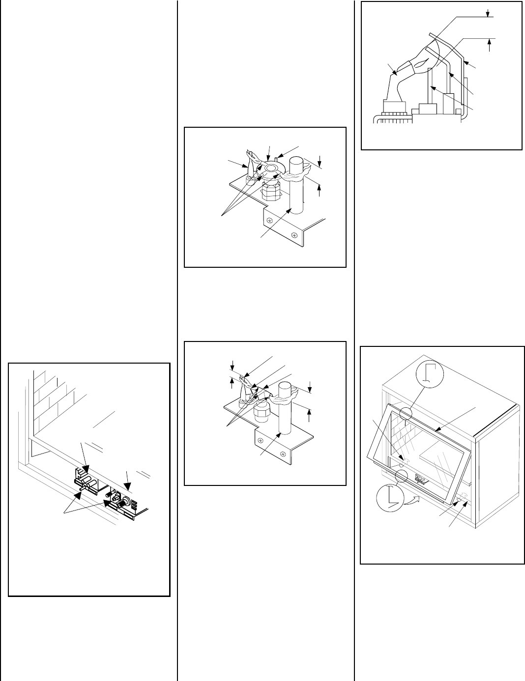
- INSTALLING THE GLASS DOOR
Step 9. INSTALLING THE GLASS DOOR
Retrieve the glass door. Visually inspect the
gasket on the backside of the frame. Gasket
surface must be clean, free of irregularities and
seated firmly. Position the door in front of the
firebox opening with the bottom of the door
held away from the fireplace
(Figure 53 )
. Hook
the top flange of the door frame over the top of
the firebox frame.
Let the bottom of the door frame swing gently
in towards the fireplace ensuring that the gas-
ket seats evenly as the door frame draws shut.
Fasten the two latches located underneath the
firebox floor to the door's vee-flange. Close
both the latches securely.
Electronic Appliance Checkout
To light the burner, turn ‘ON’ the optional
remote wall switch and turn the gas control
switch to the “ON” position. Ensure the ignitor
lights the pilot. The pilot flame should engulf
the flame rod as shown in
Figure 52
.
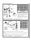
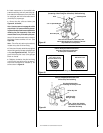
Figure 50
1/8" Min
(3 mm)
Thermocouple
Ignitor Rod
Hood
3/8" Min
(9 mm)
Thermopile
MILLIVOLT HONEYWELL
Pilot
Nozzels
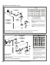
Figure 49
Sit and Honeywell Millivolt Gas Valve
Showing Piezo Ignitor Location (Each Unit is
Equipped with Only One of these Gas Valves)
Piezo
Ignitor
SIT Gas Valve
Honeywell
Gas Valve
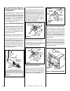
Step 8. CHECKING APPLIANCE OPERATION
With gas line installed run initial system check-
out before closing up the front of the unit.
Follow the pilot lighting instructions provided
in the Care and Operation Instructions. For
piezo ignitor location see
Figure 49
(Honeywell
millivolt appliances only).
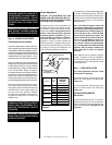
Note: Lighting Instructions are also found on
the literature tag attached to the gas valve train.
When first lighting the appliance, it will take a
few minutes for the line to purge itself of air.
Once purging is complete, the pilot and burner
will light and operate as indicated in the in-
struction manual. Subsequent lightings of the
appliance will not require such purging. In-
spect the pilot flame (remove logs, if neces-
sary, handling carefully).
The packaged logs are located within the
firebox. The vermiculite, decorative volcanic
stone and glowing embers are packaged sepa-
rately in plastic bags located in the control area
of the fireplace. Refer to the Log Set Place-
ment Guide for detailed placement instruc-
tions for the logs, vermiculite, decorative vol-
canic stone and glowing embers.
Step 7. INSTALLING LOGS, VERMICULITE,
DECORATIVE VOLCANIC STONE AND
GLOWING EMBERS