


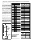
9
NOTE: DIAGRAMS & ILLUSTRATIONS ARE NOT TO SCALE.
DETAILED INSTALLATION STEPS
The appliance is shipped with all gas controls
and components installed and pre-wired.
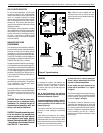
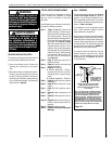
1. Remove the shipping carton. Remove the
shipping pad, exposing the front glass
door.
2. Open the two latches (located under the fire-
boxoor)securingtheglassdoor.Remove
the door by tilting it outward at the bottom
and lifting it up. Set the door aside protecting
it from inadvertent damage. See Removing
Glass Panels on Page 30.
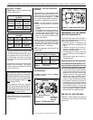
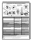
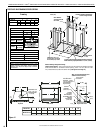
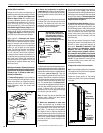
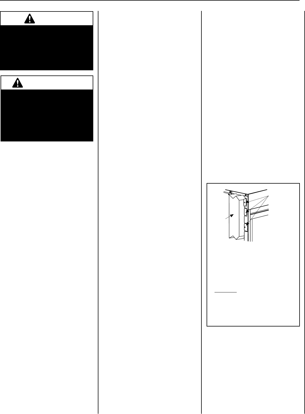
Figure 10
Note: The nailing flanges, combustible members
and screw heads located in areas directly adjacent
to the nailing flanges, are EXEMPT from the 1/2”
clearance to combustible requirements for the
firebox outer wrapper. Combustible framing may be
in
direct contact with the nailing flanges and may
be located closer than 1/2” from screw heads and
the firebox wrapper in areas adjacent to the nailing
flanges. Frame the opening to the exact dimensions
specified in the framing details of this manual.
Nailing Flanges Are
Provided At All Four
Corners At 5/8”, 1/2”
And Flush Settings
Side
Framing
Unit
Nailing Flange
Left Side Front Corner of Fireplace Shown
(Right Side Requirements the Same)
Unit Being Secured By Its Nailing Flanges
To The Framing
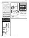
WARNING
Failure to position the parts in
accordance with these diagrams
or failure to use only parts specifi-
cally approved with this appliance
may result in property damage or
personal injury.
AVERTISSEMENT
Risque de dommages ou de
blessures si les pièces ne sont
pas installées conformément à
ces schémas et ou si des pièces
autres que celles spécifiquement
approuvées avec cet appareil sont
utilisées.
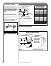
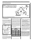
Step 1. FRAMING
Frame these appliances as illustrated in Figures
11 and 12 on Pages 10 and 11 (Figure 12
applies to corner framing installations only).
All framing details must allow for a minimum
clearance to combustible framing members as
shown in Table 5 on Page 8.
Iftheapplianceistobeelevatedaboveoor
level, a solid continuous platform must be
constructed below the appliance.
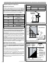
Headers may be in direct contact with the appli-
ance top spacers when they are bent up vertically
maintaining the 3" clearance to the fireplace top,
but must not be supported by them or notched
to fit around them. All construction above the
appliance must be self-supporting. DO NOT use
the appliance for structural support.
The fireplace should be secured to the side
framing members using the unit's nailing
anges-onetopandbottomoneachsideof
the fireplace front. See Figure 10. Use 8d nails
or their equivalent.
TYPICAL INSTALLATION SEQUENCE
The typical sequence of installation is outlined
below. However, each installation is unique
and may result in variations to the steps
described.
See the Page numbers references in the follow-
ing steps for detailed procedures.
Step 1. (Pages 10 and 11) Construct the
appliance framing. Position the ap-
pliance within the framing and secure
with nailing brackets. Bend up the
appropriate header spacing guides for
the drywall/finish material thickness
to be used (see Figure 47 on Page
32). Bend up the outer pair for 1/2"
materials and the inner pair for 5/8"
materials. Bend out the appropriate
nailingangesforthedrywall/nish
materialtobeused.Nailinganges
areprovidedforushframing,1/2
inch and 5/8 inch framing depths
(see Figure 10).
Step 2. (Page 11) Route gas supply line to
appliance location.
Step 3. (Page 12) Install the vent system and
exterior termination.
Step 4. (Page 24) Field Wiring
a. Millivolt Appliances – Bring in
electrical service line for forced air-
circulating blower (optional equip-
ment).
b. Electronic Appliances – Field wire.
Step 5. (Page 25) Install blower kit (optional
equipment).
Step 6. (Page 26) Make connection to gas
supply.
Step 7. (Page 27) Verify appliance opera-
tion.
Step 8. (Page 28) Install contemporary me-
dia.
Step 9. (Page 30) Install glass door assem-
bly.
Step 10. (Page 30) Adjust burner primary air
shuttertoachieveproperameap-
pearance.
Step 11. (Page 32) Install the hoods.
Step 12. (Page 33) Attach Safety in Operation
Warnings.
LENNOXHEARTHPRODUCTS•MERIT
®
SERIESDIRECT-VENTCONTEMPORARYDESIGNGASFIREPLACES•MODELMLDVTCD-35•INSTALLATIONINSTRUCTIONS