


37
NOTE: DIAGRAMS & ILLUSTRATIONS ARE NOT TO SCALE.
* Standard size installed at factory
** Standard size in LP conversion kit
• Part /Cat. Number
LENNOXHEARTHPRODUCTS•MERIT
®
SERIESDIRECT-VENTCONTEMPORARYDESIGNGASFIREPLACES•MODELMLDVTCD-35•INSTALLATIONINSTRUCTIONS
Millivolt Appliances
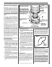
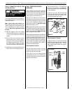
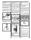
Step 5. SIT Systems - Refer to Figure 50 on
Page 37 and the instructions provided with
the kit. Using a Torx T20 (with 1/4" shank and
centerhole),toolorstandardatscrewdriver
remove and discard the three pressure regulator
mounting screws. Remove the pressure regu-
lator, spring, poppet, diaphragm and bushing.
Discard all removed components.
Ensure the rubber gasket installed on the back of
the replacement pressure regulator is properly
positioned and install the new pressure regula-
tor using the new screws supplied with the kit.
Tighten screws to 25 In. lb. torque.
Pressure
Regulator
Remove
These
Components
Pilot
Orifice
Electronic Appliances
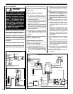
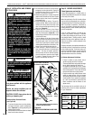
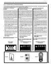
Step 7. Dexen Electronic Valves - See Figure
52 and the instructions provided with the kit.
Remove and discard the two pressure regula-
tor mounting screws. Remove the pressure
regulator and diaphragm. Discard all removed
components. Ensure the provided diaphragm
is installed properly onto the replacement
pressure regulator and install the new pres-
sure regulator using the new screws supplied
with the kit. Tighten screws.
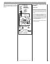
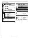
See Figure 53 and replace the pilot orifice as
follows: Remove pilot hood assembly to access
the phillipped pilot orifice. Remove and replace
the orifice with the one provided with the kit.
Exercise extreme care to prevent damage to
or breakage of the igniter assembly.
Step 6. See Figure 51 and remove the pilot
hood assembly to access the hexed pilot orifice.
Remove and replace the orifice with the one
provided with the kit.
Figure 50
Figure 51
Note: If the igniter is damaged, a re-
placement kit is available, order Catalog
Number 87L54.
Step 9. Reassemble the remaining components
by reversing the procedures outlined in the
preceding steps.
Step 10. Attach the conversion label provided
in the conversion kit to the rating plate on the
appliance.
Step 11. Turn on gas supply and test for gas
leaks. See Test All Connections For Gas Leaks
on Page 27.
Step 12. Attach manometer to the manifold
side pressure test fitting and verify manifold
pressure reads 3.5 inches water column (0.87
kPa) for natural gas, and 10.0 inches water
column (2.49 kPa) for propane gas.
ALWAYS TEST PRESSURES WITH THE VALVE
REGULATOR CONTROL AT THE HIGHEST
SETTING.
All Models
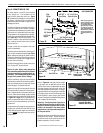
Step 8. (Refer to Figure 49 on Page 36 and
Figure 54)
VERIFY THE PROPER ORIFICE SIZE
BEFORE INSTALLING IT.
A. Remove the orifice from the manifold and
replace it with the one provided in the kit. See
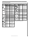
Table 9 for orifice sizes for natural and pro-
pane models. Figure 54 illustrates the orifice.
UsepipejointcompoundorTeontapeonall
pipe fittings before installing (ensure propane
resistant compounds are used in propane ap-
plications, do not use pipe joint compounds
onarettings).
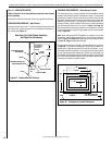
B. Retrieve the burner and slide the venturi
tube over the orifice. Set the shutter adjusting
opening as shown in Figure 49 on Page 36.
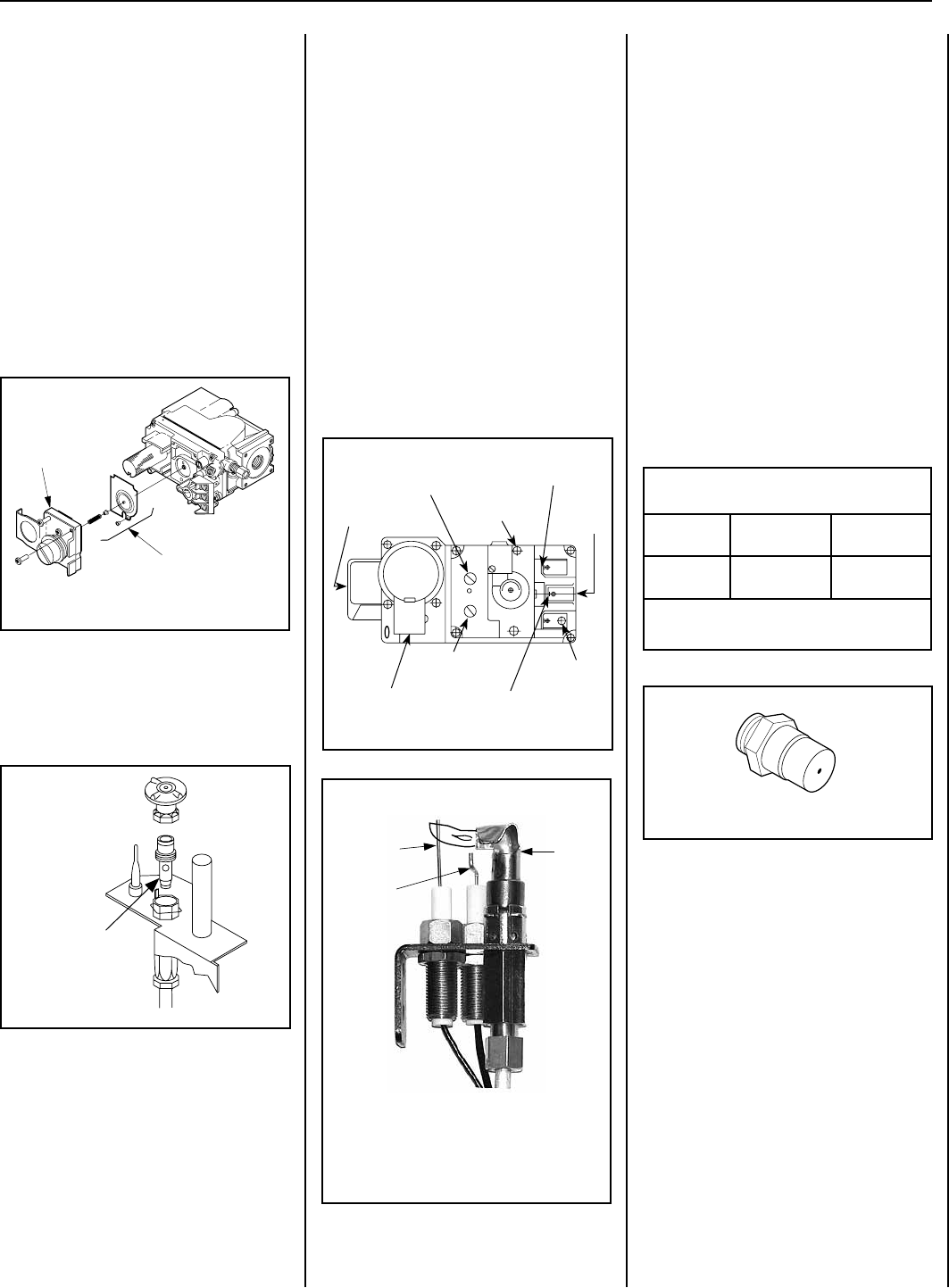
Figure 53
Figure 54
ELECTRONIC
Pilot
Hood
Sensor
Igniter
Burner Orifice Sizes
Elevation 0-4500 feet ( 0-1372 meters)
Model
Series
Nat.Gas
drill size (inches)
Propane
drill size (inches)
MLDVTCD-35
#49 (0.073")
*
21L82 •
(0.045")
**
75L10•
Table 9
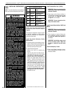
Figure 52 - Dexen Electronic Gas Valve
Supply Gas
Inlet
Pressure-Tap
(Manifold)
Regulator
Mounting
Screw
Burner Stage
Terminal
Gas
Outlet
To Burner
Ground (TP)
Pilot Stage
Terminal
Pilot Gas Outlet
Pressure-Tap
(Inlet)
PILOT
OUT
VENT
LO
TH
TP
TH
TP
HI
IN
IN