


25
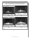
NOTE: DIAGRAMS & ILLUSTRATIONS ARE NOT TO SCALE.
LENNOXHEARTHPRODUCTS•MERIT
®
SERIESDIRECT-VENTCONTEMPORARYDESIGNGASFIREPLACES•MODELMLDVTCD-35•INSTALLATIONINSTRUCTIONS
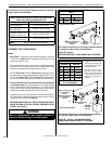
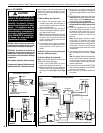
Note: No batteries to be installed in the battery
holder until a power outage, or if the appli-
ance is to be operated solely with two (2) "D"
batteries.
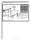
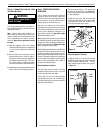
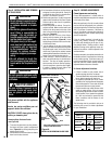
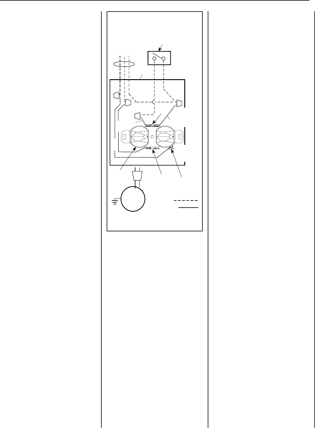
BLOWER CONTROL CIRCUIT WIRING
120V, 60HZ, 1PH
Factory Wired
Ground
Field Wired
Junction Box
Tab Intact
Tab
Broken
Plug blower
into this
receptacle
neerG - dnuorG
* Wall-mounted
ON/ OFF Blower
Switch or Variable
Speed Control Switch.
Blower
etihW - lar
t
ueN
120 VAC - Black
Green
Ground
Screw
White
Green
Neutral
Side of
Receptacle
Hot
Side of
Receptacle
Red
Black
Figure 37 - J-BOX WIRING
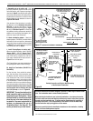
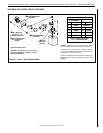
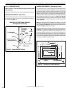
Step 5. WIRING - OPTIONAL FORCED AIR
BLOWER KIT
Blower Access
Blower access is through the firebox bottom.
Remove the front panel, the porcelain panels,
thesub-oor,removetheburnerandremove
ten screws securing the GTA assembly to the
firebox.
An electrical outlet box is provided for the instal-
lation of the FBK-100 and FBK-200 forced air
blower kit. Electrical power must be provided
to this box to operate these blowers. Install the
blower kit according to the installation instruc-
tions provided with the kit.
Reposition and reinstall the GTA assembly,
burnerandsub-oor.