


14
NOTE: DIAGRAMS & ILLUSTRATIONS ARE NOT TO SCALE.
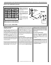
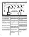
Vertical (Offset) Installation
Analyze the vent routing and determine the
quantities of vent sections and number of elbows
required. Refer to Vertical Vent Figures and
Tables on Pages 16 and 17 to select the type
of vertical installation desired. Vent sections
are available in net lengths of 4-1/2" (114 mm),
10-1/2" (267 mm), 22-1/2" (572 mm), 34-1/2"
(876 mm) and 46-1/2" (1181 mm). Refer to the
Vent Section Length Charts on Page 13 for an
aid in selecting length combinations. Elbows are
available in 90° and 45° configurations. Refer
to Figure 19 on Page 15 for the SV4.5E45 and
SV4.5E90 elbow dimensional specifications.
Where required, a telescopic vent section
(SV4.5LA) may be used to provide the installer
with an option in installing in tight and confined
spaces or where the vent run made up of fixed
length pieces develops a joint in a undesirable
location, or will not build up to the required
length. The SV4.5LA Telescopic Vent Section
has an effective length of from 1-1/2" (38 mm)
to 7-1/2" (191 mm). The SV4.5LA is fitted with
a locking inclined channel end (identical to a
normal vent section component) and a plain end
with 3 pilot holes. Slip the plain end over the
locking channel end of a standard SV4.5 vent
component the required distance and secure
with three screws.
Maintain a minimum 1" (25 mm) clearance to
combustible materials for all vertical elements.
Clearances for all horizontal elements are 3"
(76 mm) on top, 1" (25 mm) on sides and 1"
(25 mm) on the bottom.
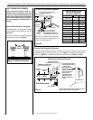
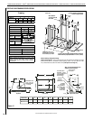
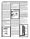
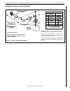
A. Frame ceiling opening - Use a plumb line
from the ceiling above the appliance to locate
center of the vertical run. Cut and/or frame an
opening, 10-1/2" x 10-1/2" (267mm x 267mm)
inside dimensions, about this center mark
(Figure 16).
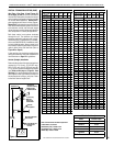
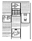
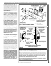
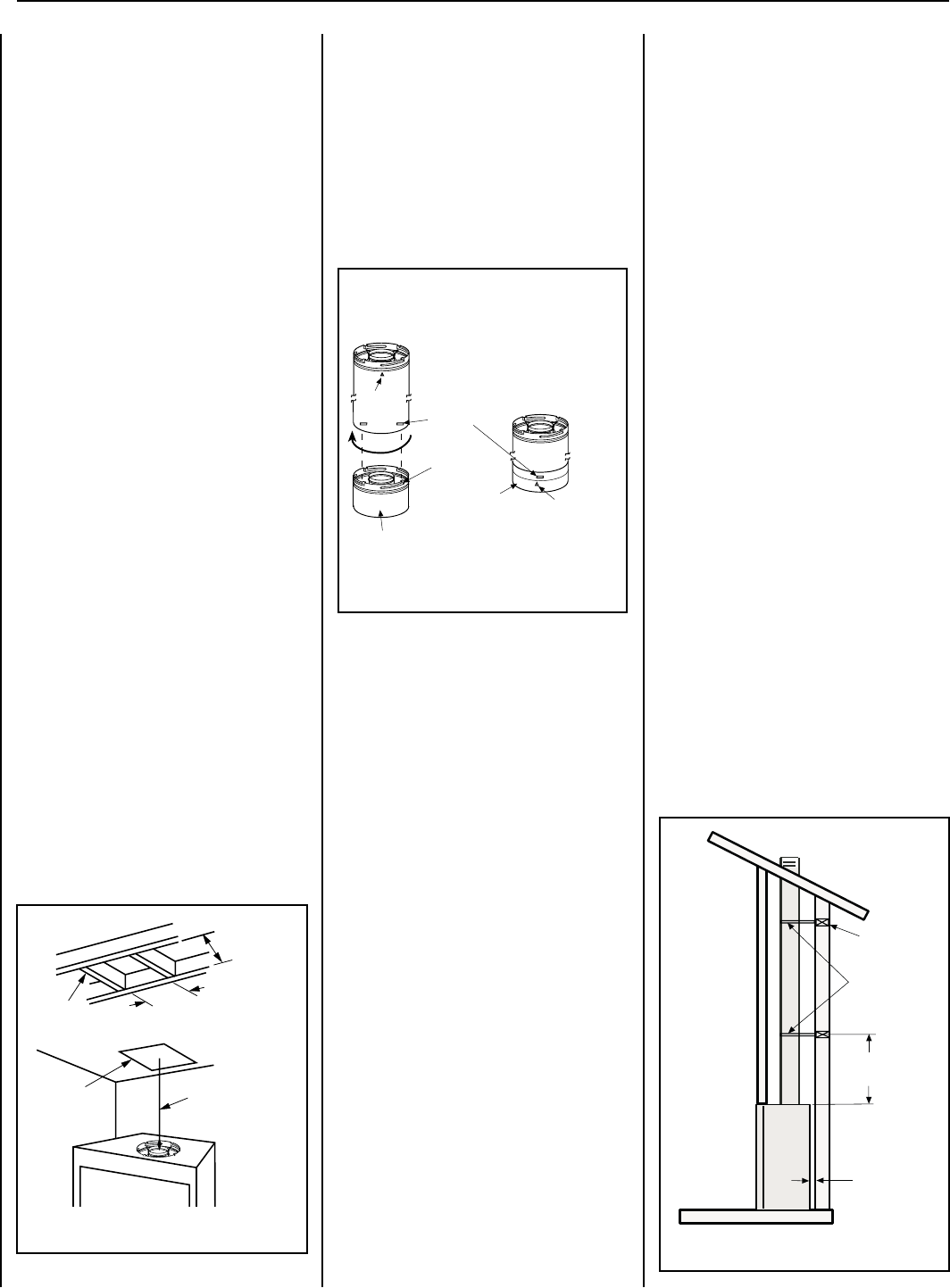
To attach a vent component to the appliance collar,
align the dimpled end over the collar, adjusting the
radial alignment until the four locking dimples are
aligned with the inlet of the four inclined channels
on the collar (refer to Figure 17). Push the
vent component against the collar until it fully
engages, then twist the component clockwise,
running the dimples down and along the incline
channels until they seat at the end of the chan-
nels. The unitized design of the Secure Vent™
components will engage and seal both the inner
and outer pipe without the need for sealant or
screws. If desired, a #6 x 1/2" screw may be
used at the joint, but is not required as the pipe
will securely lock when twisted.
Note: An elbow may also be attached to the
appliance collar. Attach in the same manner
as you would a vent section.
C. Attach vent components to each other
- Other vent sections may be added to the
previously installed section in accordance with
the requirements of the vertical vent Figures
and Tables. To add another vent component
to a length of vent run, align the dimpled end
over the inclined channel end of the previously
installed section, adjusting the radial alignment
until the four locking dimples are aligned with
the inlets of the four incline channels of the
previous section.
B. Attach vent components to appliance
- Secure Vent SV4.5 direct-vent system compo-
nents are unitized concentric pipe components
featuring positive twist lock connections (see
Figure 17).
All of the appliances covered in this document
are fitted with collars having locking inclined
channels. The dimpled end of the vent com-
ponents fit over the appliance collar to create
the positive twist lock connection.
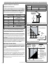
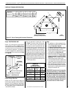
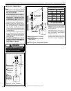
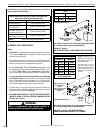
Blocking
Support Straps
(Plumber's tape)
8 feet (2.4 m)
Maximum
1/2 inch (12.7
mm) minimum
clearance to
combustibles
Figure 18
LENNOXHEARTHPRODUCTS•MERIT
®
SERIESDIRECT-VENTCONTEMPORARYDESIGNGASFIREPLACES•MODELMLDVTCD-35•INSTALLATIONINSTRUCTIONS
Push the vent component against the previous
section until it fully engages, then twist the
component clockwise running the dimples down
and along the incline channels until they seat at
the end of the channels. This seating position
is indicated by the alignment of the arrow and
dimple as shown in Figure 17.
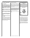
D. Install firestop/spacer at ceiling - When us-
ing Secure Vent, use SV4.5VF firestop/spacer
at ceiling joists; when using Secure Flex, use
SF4.5VF firestop/spacer. If there is living space
above the ceiling level, the firestop/spacer
must be installed on the bottom side of the
ceiling. If attic space is above the ceiling, the
firestop/spacer must be installed on the top
side of the joist.
Route the vent sections through the framed
opening and secure the firestop/spacer with
8d nails or other appropriate fasteners at
each corner. Remember to maintain 1" (25
mm) clearance to combustibles, framing
members, and attic or ceiling insulation
when running vertical chimney sections.
Attic insulation shield (H3907) may be used
to obtain the required clearances indicated
here. See installation accessories Pages 34
and 35. The gap between the vent pipe and
a vertical firestop can be sealed with non-
combustible caulking.
E. Support the vertical vent run sections -
Note - Proper venting support is very important.
The weight of the vent must not be supported
by the fireplace in any degree.
Support the vertical portion of the venting
system every 8 feet (2.4m) above the fireplace
vent outlet.
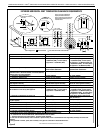
Figure 17
Align the dimple (4 places) of the
upper vent section with the opening
of the locking incline channel on
the lower vent section or appliance
collar. Twist vent component
clockwise to engage and seal until
arrow and dimple align.
Dimple
Locking
Incline
Channel
Connected Vent
Sections
Arrow
Arrow
Appliance Collar or
Vent Section
Figure 16
10-1/2” Min.
(267mm)
10-1/2” Min.
(267mm)
Plumb
Bob
Roof
Framing
Ceiling
Framing