


30
NOTE: DIAGRAMS & ILLUSTRATIONS ARE NOT TO SCALE.
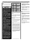
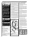
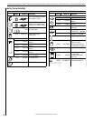
Air Shutter Adjustment Guidelines:
Amount of
Primary Air
Flame
Color
Air Shutter
Adjustment
If air shutter is
closed too far
Flame will
be orange
Air shutter
gap should be
increased
If air shutter is
open too far
Flame will
be blue
Air shutter
gap should be
decreased
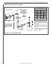
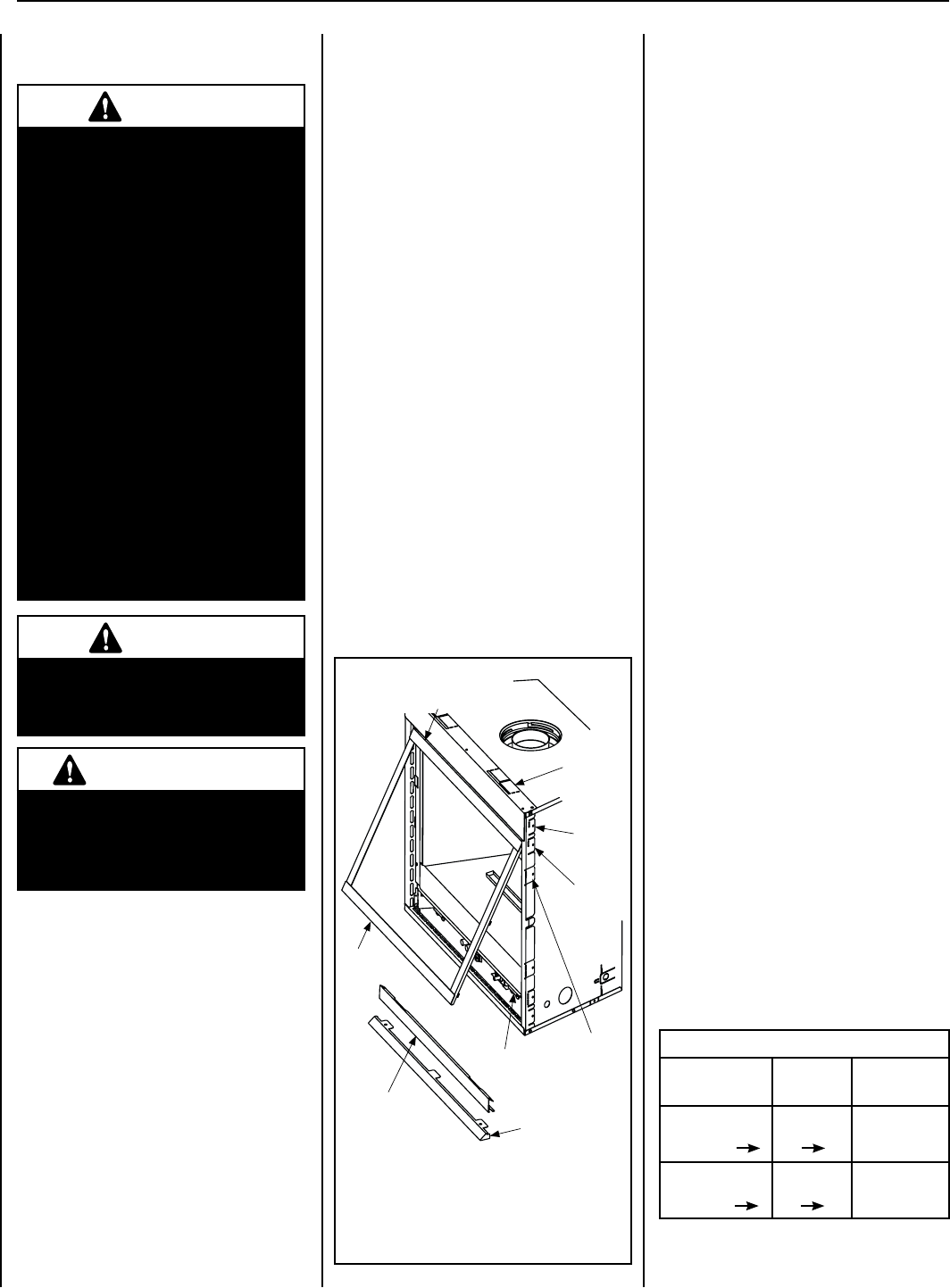
Figure 44 -
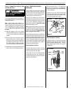
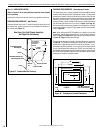
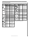
INSTALLING OR REMOVING GLASS DOOR
Control
Compartment
Panel
Hood
Glass
Door
Header
Spacing
Top
Standoffs
Flush
Nailing
Flange
1/2”
Nailing
Flange
5/8”
Nailing
Flange
Glass Door
Spring Latch
Ensure Gasket Is Not Rolled
Up Into Door Frame Channel
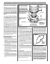
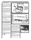
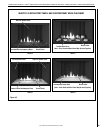
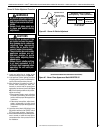
Step 10. BURNER ADJUSTMENTS
Flame Appearance and sooting
Properameappearanceisaamewhichis
blue at the base and becomes yellowish-orange
inthebodyoftheame.
Whentheapplianceisrstlit,theentireame
may be blue and will gradually turn yellowish-
orange during the first 15 minutes of operation.
After15minutesofoperation,iftheameis
blue,oriftheameisorangewithevidenceof
sooting (black tip), the air shutter opening may
need to be adjusted.
If the air shutter openings is closed too far,
sooting may develop. Sooting is indicated
by black puffs developing at the tips of very
longorangeames.Sootingresultsinblack
deposits forming on the appliance inside sur-
faces and on exterior surfaces adjacent to the
vent termination.
Sooting is caused by incomplete combustion in
theamesandlackofcombustionairentering
the air shutter opening. To achieve a warm yel-
lowish-orangeamewithanorangebodythat
does not soot, the shutter opening must be
adjusted between these two extremes.
Air Shutter Adjustment Guidelines
• Ifthereissmokeorsootpresent,theair
shutter opening should be increased.
• Themoreoffsetsintheventsystem,thelarger
the air shutter opening will need to be.
• Anapplianceoperatedwiththeairshutter
openedtoofar,mayhaveamesthatappear
blue and transparent. These weak, blue and
transparentamesaretermedanemic.
• Propanemodelsmayexhibitameswhich
candle or appear stringy. If this is present
and persists, adjust the air shutter to a more
closed position, then operate the appliance
for a few more minutes to ensure that the
ame normalizes and the ames do not
appear sooty.
The following chart is provided to aid you in
achieving the correct air shutter adjustment
for your installation.
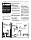
3. Pull the bottom of the door out a few inches
and grasp it on the right and left. Gently lift
to release the door from its channel above
the door. Pull the door forward.
4. Retrieve the glass door. Visually inspect the
gasket on the backside of the frame. Gasket
surface must be clean, free of irregularities
and seated firmly.
5. Inspect the gasket for defects. Ensure it is
properly located. Make sure the bead is not
rolled up into the channel at the top of the
door,butremainsatagainstthetopofthe
glass (see Figure 44).
6. Position the door in front of the firebox
opening with the bottom of the door held
away from the fireplace (Figure 44). Hook
thetopangeofthedoorframeoverthetop
of the firebox frame.
7. Let the bottom of the door frame swing
gently in towards the fireplace ensuring that
the gasket seats evenly as the door frame
draws shut. Fasten the two latches located
underneaththereboxoortothedoor'svee-
ange.Closeboththelatchessecurely.
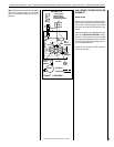
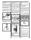
8. Install the hood. Note the location of the
three clips inside the top air channel above
the door. The clips are equally spaced on
the top surface of the air channel opening.
Use a screwdriver to open the clips slightly
if needed. Engage the back edge of the
eyebrow into the clips to secure.
Note: When installing the glass door, ensure the
spacing on both sides are equal.
LENNOXHEARTHPRODUCTS•MERIT
®
SERIESDIRECT-VENTCONTEMPORARYDESIGNGASFIREPLACES•MODELMLDVTCD-35•INSTALLATIONINSTRUCTIONS
Step 9. INSTALLATION AND REMOVAL
OF GLASS DOOR
Only doors certified with the appliance
shall be used.
Seules des portes certifiées pour cet
appareil doivent être utilisées.
CAUTION: DO NOT abuse glass door by
striking or slamming shut.
Removing Glass Enclosure Panels
(see Figure 44)
1. To access the glass door securing latches,
first open the lower control compartment
door (Figure 44) by sliding and pulling the
bottom panel forward.
2. Pull the latches forward and down to release
them from the door channel.
WARNING
• Do not attempt to substitute the
materials used on these doors,
or replace cracked or broken
glass.
• Handle this glass with extreme
care! Glass is susceptible to
damage – Do not scratch or
handle roughly while reinstall-
ing the glass door frame.
• The glass door(s) of this appli-
ance must only be replaced as
a complete unit as provided
by the manufacturer. Do not
attempt to replace broken,
cracked or chipped glass sepa-
rately.
• Do not attempt to touch the
front enclosure glass with your
hands while the fireplace is in
use.
WARNING
Do not operate appliance with
the glass front removed, cracked
or broken.
AVERTISSEMENT
Ne pas utiliser l'appareil si le
panneau frontal en verre n'est
pas en place, est craqué ou
brisé.