


26
NOTE: DIAGRAMS & ILLUSTRATIONS ARE NOT TO SCALE.
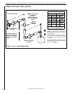
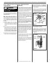
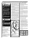
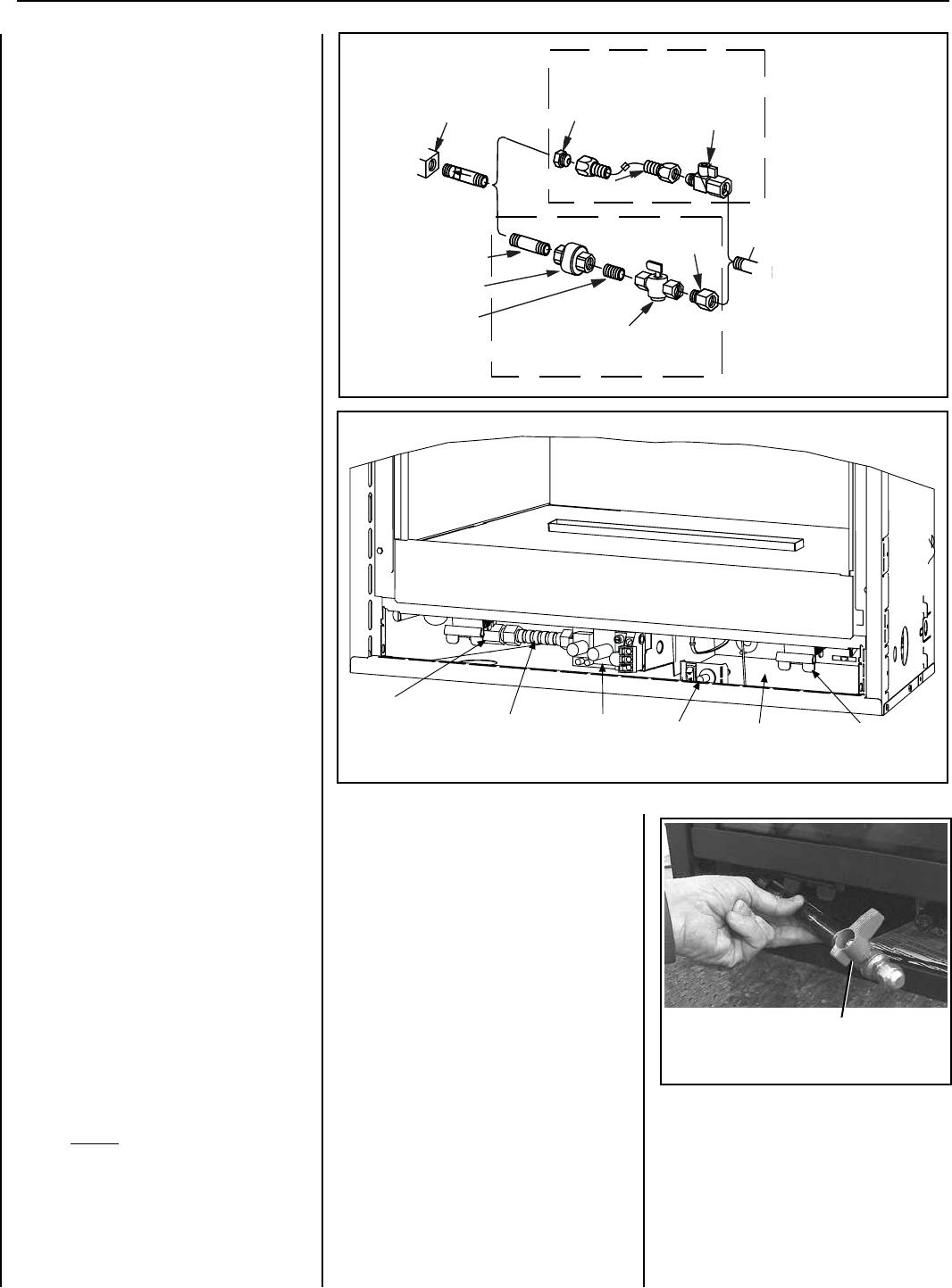
Length Of Pipe With
Attached Shut-Off Valve
Figure 40
LENNOXHEARTHPRODUCTS•MERIT
®
SERIESDIRECT-VENTCONTEMPORARYDESIGNGASFIREPLACES•MODELMLDVTCD-35•INSTALLATIONINSTRUCTIONS
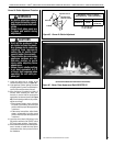
Gas Flex Line
Gas Shut-Off
Valve
Valve
Piezo
Spring Door
Latch
Lower Control
Compartment
Figure 39
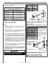
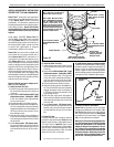
Refer to Figure 40 and insert the last length
of gas pipe with its attached shut-off valve
into the lower control compartment and pass
it through the gas line access hole on the left
side of the appliance outer wrapper. Using ap-
propriate materials for the gas type, thread the
last length of pipe into the end of the gas vent
run and tighten in place using a pipe wrench
external to the appliance between the appliance
outer wrapper and the framing.
Important: Turn the last piece of gas pipe in
the last fitting until the shut-off valve is posi-
tioned in a way that allows the shut-off valve
handle to be accessed in the lower control
compartment, easily operated throughout its
full range of motion.
Bringtheex-linetotheshutoffvalvebyhand
andalignthearettings.Tightenthettings
by hand, and then use an open end wrench to
tighten completely, 1/4 turn at a time.
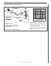
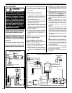
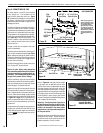
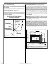
Step 6. CONNECTING GAS LINE
All codes require a shut-off valve mounted
in the supply line. The orientation of the
shut-off valve should face the front. Figure
38 illustrates two methods for connecting the
gas supply. A Sediment Trap is recommended
to prevent moisture and debris in gas line from
damaging the valve.
Theex-linemethodisacceptableintheU.S.A.
where local codes permit, however, Canadian
requirements vary depending on locality. Instal-
lation must be in compliance with local codes.
Theseappliancesareequippedwithagasex-
line for use in connecting the unit to the gas line.
See Figure 38 forex-linedescription.The
ex-lineisratedforbothnaturalandpropane
gas. A manual shut off valve is also provided
withtheex-line.
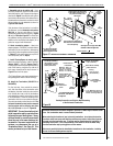
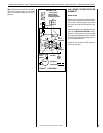
The gas control valve is located in the lower
control compartment.
Access the valve compartment by removing the
lower control compartment panel (see Figure
39) by sliding and pulling the panel forward.
The panel is mounted at the extreme right and
left hand sides, through slots. Engage the tabs
into the slots in the panel.
The millivolt and electronic control valve has a
3/8" (10 mm) NPT thread inlet port.
Secure all joints tightly using appropriate
tools and sealing compounds (ensure propane
resistant compounds are used in propane ap-
plications). It is recommended to seal around
the gas line to prevent cold air leakage.
Gas line connection may be performed largely
outside of the confines of the control compart-
ment and without having to enter the firebox
behind the glass. Proceed as follows:
Acquire the shut-off valve and gas lex line and
pull the assembly forward out of the compart-
ment. Separate the shut-off valve from the gas
ex-line.Determinethelengthofpipeneeded
to route the gas line from the last fitting (shown
in Figure 13 on Page 11) to a point within the
control compartment that will allow the shut-
off valve to be easily attached by hand to the
gasex-line.
Using pipe-dressing materials appropriate for
the gas type, securely affix the shut-off valve
to this determined pipe length at a convenient
location outside of the appliance lower control
compartment.
Gas
Valve
3/8" NPT x
Flare Fitting
3/8" Flex Tubing
3/8" Nipple
3/8" Union
3/8" Close
Nipple
3/8" Shut-off Valve
1/2" x 3/8"
Reducer
Gas
Stub
1/2" x 3/8" Flare
Shut-off Valve
Gas Solid Line Connector
Gas Flex Line Connector
*Sediment
Trap
3"
Min
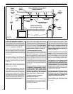
Note: The gas supply line
must be installed in accor-
dance with building codes
by a qualified installer
approved and/or licensed
as required by the locality.
In the Commonwealth of
Massachusetts, installation
must be performed by a
licensed plumber or gas
fitter.
Figure 38
GAS CONNECTION