


10
NOTE: DIAGRAMS & ILLUSTRATIONS ARE NOT TO SCALE.
LENNOXHEARTHPRODUCTS•MERIT
®
SERIESDIRECT-VENTCONTEMPORARYDESIGNGASFIREPLACES•MODELMLDVTCD-35•INSTALLATIONINSTRUCTIONS
A
B
C
7
(178)
5-1/8
12-1/8
(308)
10-1/2
(
267
)
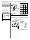
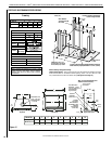
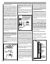
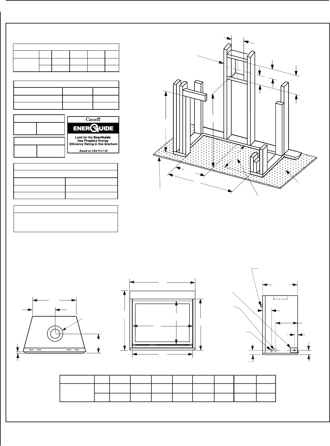
VENT FRAMING -
TOP VENT WITH ONE
90
°
ELBOW
Framing should be constructed
of 2x4 or larger lumber
Inches (mm)
D
(130)
D is the required framing depth dimension when the
finish material (drywall) thickness is 1/2 in. (13mm)
A
1/2
Raised Platform
Or Floor
Add Minimum Of 18” For
Raised Platform If Installing
With Contemporary Facade.
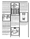
FIREPLACE AND FRAMING SPECIFICATIONS
Vent Size
Co-axial DV
Vent Size
4-1/2" Inner
7-1/2" Outer
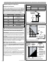
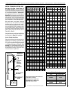
Vertical Venting Through the Ceiling:
Frame ceiling opening - Use a plumb line from the ceiling above the appliance to locate
center of the vertical run. Cut and/or frame an opening, 10-1/2" x 10-1/2" (267 mm x 267
mm) inside dimensions, about this center mark (see Figure 16 on Page 14).
Input (BTU) - MV & Electronic
Natural & Propane Gas
Model Input Rate (BTU / HR)
MLDVTCD-35N 14,500
MLDVTCD-35P 13,500
Efficiencies %
Natural Gas Propane
Model P4 P4
MLDVTCD-35
48 51
Viewable Glass Size
35" Model
29-1/4" Wide
20-1/4" High
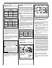
Figure 11
Framing
Framing Dimensions
Model No. A B C D
MLDVTCD-35
in. 35-1/4 35-1/4 39-1/4 16
mm 895 895 997 406
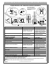
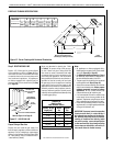
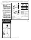
.oNledoM E F G H J K
L M
.ni
mm
32-1/4
819
28-1/8
715
23-1/4
587
32
813
35-1/4
892
25
635
12-1/2
317
33
838
MLDVTCD-35
J
Front View
H
G
F
E
M
K
L
Top View
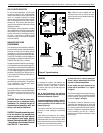
*CONCENTRIC FLUE
FLUE - 4-1/2 (114)
COMBUSTION AIR
- 7-1/2 (190)
9-1/4 (235)
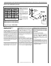
1/2
(13)
16 (406)
1-5/8
(42)
NOTE - Eyebrow
hood shown.
GAS INLET
KNOCKOUT
(Other Side)
Right Side View
5-7/8
(149)
NOTE - It is recommedned that the gas be studed in from the left
side only.
3 (76)
3 (76)
9-1/2
(241)
ELECTRICAL INLET
KNOCKOUT - 2-3/4 X 2
(70 X 51) COVER PLATE
(With KNOCKOUT -
Right Side Only)
OPTIONAL
ELECTRICAL
INLET KNOCKOUT,
REQUIRING A FIELD
PROVIDED
JUNCTION BOX
(Either Side)
Notes
Diagrams, illustrations and photographs are not to scale – consult
installation instructions. Product designs, materials, dimensions,
specifications, colors and prices are subject to change or discontinu-
ance without notice.
NOTE: It is recommended that the gas be
stubbed in from the left side only.