


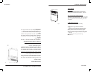
INSTALLATION INSTRU CTIONS
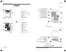
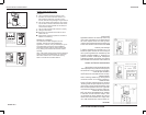
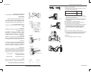
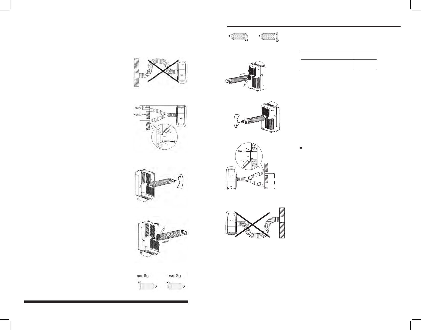
Exhaust hose installation:
The exhaust hose and adaptor must be installed or removed
in accordance with the usage mode.
COOL mode
FAN or DEHUMIDIIFY mode
Install
Remove
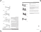
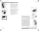
The duct can be compressed or extended moderately
according to the installation requirement, but it is
desirable to keep the duct length to a minimum.
1. Install the window Exhaust adaptor B onto the exhaust
hose as shown in Fig.18a. or Fig.18b. Refer to the previous
pages for window kit installation.
2. Place the Exhaust hose over against the air outlet opening
hook(See Fig.19) and flat the other end(See Fig.20) for
quick installation.
IMPORTANT:
DO NOT OVER BEND THE DUCT (See Fig.22)
12
Fig.18b
Fig.19
Fig.20
Fig.22
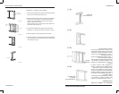
(Not applicable to the units without adaptor A, expansion
plugs and wooden screws of Accessories )
1. Prepare a hole in the wall. Install the wall Exhaust adaptor A
onto the wall(outside) by using 4 expansion plugs and
wooden screws, be sure to fix thoroughly. (See Fig.21)
2. Attach the Exhaust hose to wall Exhaust adaptor A.
The exhaust hose can be installed into the wall
.
Fig.21
max 120CM
min 30CM
Adaptor A
Expansion plug
position
Adaptor
cap
Note:
Cover the hole using the adaptor cap when not in use.
Push in
Hook
Fig.18a
INSTRUCCIONES DE INSTALACIÓN
Empuje hacia adentro
Gancho
Figura 19
Figura 20
Posición del tarugo
de expansión
Adaptador A
Tapón del adaptador
Figura 21
Instalación de la manguera de escape
La manguera de escape y el adaptador deben
instalarse o retirarse de acuerdo a la función de
uso.
Función (enfriamiento) Debe instalarse
Función (ventilador) o
DRY (deshumedecedor) Debe retirarse
1. Instale el adaptador de salida de ventana B
(boquilla plana) a la manguera de escape como
se muestra la gura 18a ó 18b. Véase las pági-
nas anteriores sobre la instalación del sistema
para ventana.
2. Para una instalación rápida, coloque la
manguera de escape en la abertura de salida de
aire utilizando el gancho (Véase la Fig. 19) y es-
tire el otro extremo (Fig. 20) como se muestra en
la gura 20.
La manguera de escape se puede instalar en la
pared (No disponible para equipos sin el adap-
tador A, los tarugos de expansión y los tornillos
de madera)
1. Prepare un agujero en la pared. Instale el
adaptador A en la pared (afuera) utilizando los
cuatro tarugos de expansión y los tornillos de
madera. Asegúrese de jarlos completamente
(Véase la gura 21)
2. Acople la manguera de escape al adaptador
de pared A.
Nota:
Cubra el agujero utilizando el tapón del adapta-
dor si no se encuentra en uso.
• La manguera de escape se puede comprimir o
estirar moderadamente de acuerdo a los requi-
sitos de instalación, pero es recomendable man-
tener la longitud de la manguera al mínimo.
IMPORTANTE:
NO DOBLE DEMASIADO LA MANGUERA DE
ESCAPE (Véase la gura 22)
ESPAÑOL 12
ENGLISH 12