


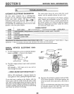
AUTOMATIC ELECTRONIC DIAGNOSTICS
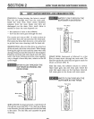
The face plate computer' has a self-diagnostic
function for the electrical system (except input
power and water meter'). The £ t '=" .....
computer monitors the electronic {Fj% '= D_
components and circuits for cor- I
rect operation. Ifa malfunction occurs, an error code
appears in the face plate display.
The chart below shows the error codes that could
appear, and the possible defects for' each code
While an err'or code appears in the display, all face
plate buttons are inoperable except the SEI_ECT
button The SELECT button remains operational so
the service person can make the Manual Initiated
Electronic Diagnostics to further isolate the defect,
and check the water meter.
CODE
Err 01
Err 02
Err 03
Err 04
Err 05
POSSIBLE DEFECT
MOST LIKELY _ _ LESS LIKELY
motor inoperative I wiring harness or connection to switch I position switch I face plate
face plate
motor inoperative / face plate
face plate / position switch
face plate
PROCEDURE FOR REMOVING ERROR CODE FROM FACE PLATE: 1 Unplug tsansformer 2. Correct defect 3 Plug-in
transformer 4. Wait for 6 minutes, The error code will remm if the defect was not corrected
,,, , , ,, ,,,,,,,,,,,,, : -
• , , , ,, ,, ...........
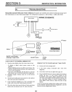
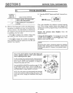
MANUAL INITIATED ELECTRONIC DIAG-
NOSTICS
1. To enter diagnostics, press and hold the SELECT
button until 000 - - shows in the display.
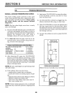
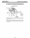
I TURB1NE SWITCHES]
nli='t ,=.=_ l
orP
1
WATER METER (A) SWITCH (B)
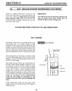
A. The first 3 digits indicate water meter operation
as follows:
000 (steady) = Soft water not in use, and no
flow through the meter.
--OPEN A NEARBY SOFT WATER FAUCET--
000 to 199 (continual) = Repeats display for
each gallon of' water passing through the meter.
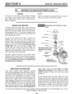
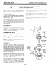
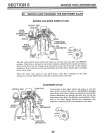
If you don't get a reading in the display, with the
faucet open, pull the sensor' from the valve outlet
port. Pass a small magnet back and forth in front of
the sensor. You should get a reading in the display, if
you get a reading, unhook the in and out plumbing
and check the turbine for binding.
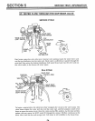
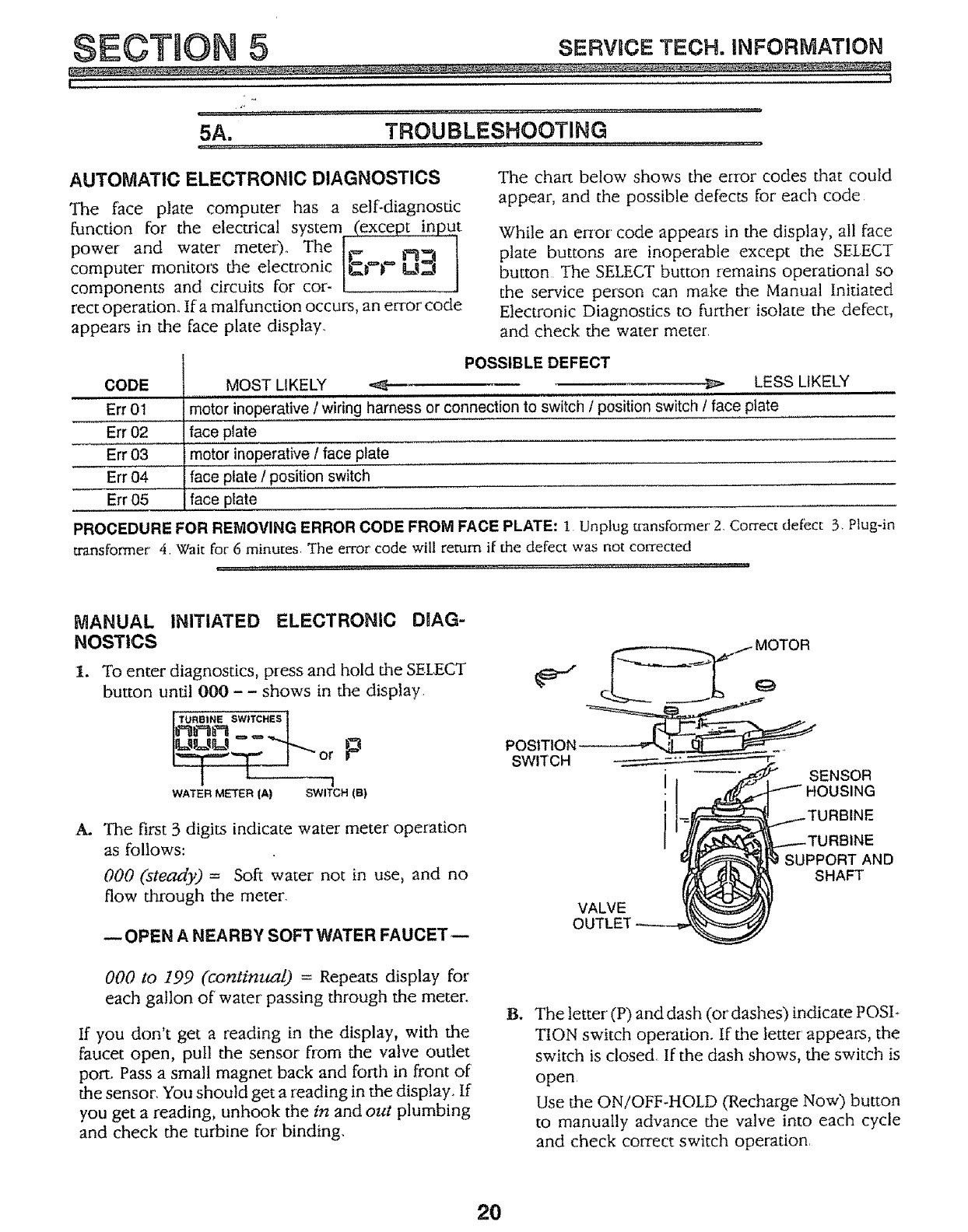
POSITION
SWITCH
VALVE
OUTLET
I
I
..,....-TURBINE
..._--TURBINE
SUPPORT AND
SHAFT
B*
The letter' (P) and dash (or dashes) indicate POSI-
TION switch operation. If the letter' appears, the
switch is closed, If the dash shows, the switch is
open.
Use the ON/OFF-HOLD (Recharge Now) button
to manually advance the valve into each cycle
and check correct switch operation.
20