


701379-UIM-C-0712
Johnson Controls Unitary Products 37
5 RED FLASHES: This fault is indicated if the limit circuit is open for
more than fifteen minutes, usually indicating that a manual-reset rollout
switch has opened. Check for proper combustion air, proper inducer
operation, and primary heat exchanger failure or burner problem. The
control will enter a hard lockout and power will have to be cycled off and
on to reset the control after the problem has been corrected.
6 RED FLASHES: This indicates that while the unit was operating, the
pressure switch opened four times during the call for heat. Check for
faulty inducer, blocked vent pipe or faulty pressure switch. The furnace
will lock out for one hour and then restart.
7 RED FLASHES: This fault code indicates that the flame could not be
established during three trials for ignition. Check that the gas valve
switch is in the ON position. Check for low or no gas pressure, faulty
gas valve, dirty or faulty flame sensor, faulty hot surface ignitor, loose
wires or a burner problem. The furnace will lock out for one hour and
then restart.
8 RED FLASHES: This fault is indicated if the flame is lost five times
(four recycles) during the heating cycle. Check for low gas pressure,
dirty or faulty flame sensor or faulty gas valve. The furnace will lock out
for one hour and then restart.
9 RED FLASHES: Indicates reversed line voltage polarity, grounding
problem or reversed low voltage transformer wires. Both heating and
cooling operations will be affected. Check polarity at furnace and
branch. Check furnace grounding. Check that flame probe is not
shorted to chassis. The furnace will not start the ignition sequence until
this problem is corrected.
10 RED FLASHES: Gas valve energized with no call for heat. The main
blower and inducer blower will run and no ignition sequence will be
started as long as this condition exists. Check gas valve and gas valve
wiring.
11 RED FLASHES: This indicates that the limit circuit has remained
open for more than five minutes and less than fifteen minutes. This con-
dition is usually caused by a failed blower motor or blower wheel. The
control will enter a hard lockout and power will have to be cycled off and
on to reset the control after the problem has been corrected.
13 RED FLASHES: This indicates that the high-fire pressure switch is
open when it should be closed. Check for a partially blocked vent pipe
or a loose or disconnected wire before replacing pressure switch.
4 AMBER FLASHES: The control is receiving a “Y” signal from the
thermostat without a “G” signal. The furnace will operate normally in
both heating and cooling, but this fault code will be displayed in order to
alert the user that there is a wiring problem. Verify that the “G” wire from
the thermostat is connected properly.
SOFT LOCKOUT: This control includes a soft lockout that will reset
automatically after one hour. This provides protection to an unoccupied
structure if a temporary condition exists causing a furnace malfunction.
An example of this is a temporary interruption in gas supply that would
prevent the furnace from lighting. The control will keep trying to light
each hour and will resume normal operation if the gas supply is
restored.
HARD LOCKOUT: Some fault conditions result in a hard lockout, which
requires power to the control to be turned off and then back on to reset
the control. The control will not automatically restart.
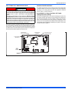
DIAGNOSTIC FAULT CODE STORAGE AND
RETRIEVAL
The control in this furnace is equipped with memory that will store up to
five error codes to allow a service technician to diagnose problems
more easily. This memory will be retained even if power to the furnace
is lost. This feature should only be used by a qualified service tech-
nician.
If more than five error codes have occurred since the last reset, only the
five most recent will be retained. The furnace control board has a but-
ton, labeled LAST ERROR that is used to retrieve error codes. This
function will only work if there are no active thermostat signals. So any
call for heating, cooling or continuous fan must be terminated before
attempting to retrieve error codes.
To retrieve the error codes, push the LAST ERROR button. The LED on
the control will then flash the error codes that are in memory, starting
with the most recent. There will be a two-second pause between each
flash code. After the error codes have all been displayed, the LED will
resume the normal slow green flash after a five second pause. To
repeat the series of error codes, push the button again.
If there are no error codes in memory, the LED will flash two green
flashes. To clear the memory, push the LAST ERROR button and hold it
for more than five seconds. The LED will flash three green flashes when
the memory has been cleared and the button is released, then will
resume the normal slow green flash after a five-second pause.
IGNITION CONTROL FLAME SENSE LEVELS
Normal flame sense current is approximately
3.7 microamps DC (µa)
Low flame signal warning starts at 1.5 microamps.
Low flame signal control lockout point is
0.1 microamps DC (µa)