


701379-UIM-C-0712
30 Johnson Controls Unitary Products
Specially Engineered Installations
The above requirements shall be permitted to be waived where special
engineering, approved by the authority having jurisdiction, provides an
adequate supply of air for combustion and ventilation.
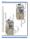
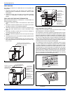
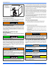
VENT BLOWER ROTATION
For ease of venting, the vent blower may be rotated 90° in either direc-
tion. For upflow installations the vent may exit through the top or either
side of the cabinet. For downflow installations, the vent blower must be
rotated so that the vent exits through either side of the cabinet. See Fig-
ures 24-27 for details.
SECTION VIII: START-UP AND
ADJUSTMENTS
The initial start-up of the furnace requires the following additional
procedures:
When the gas supply is initially connected to the furnace, the gas piping
may be full of air. In order to purge this air, it is recommended that the
ground union be loosened until the odor of gas is detected. When gas is
detected, immediately retighten the union and check for leaks. Allow
five minutes for any gas to dissipate before continuing with the start-up
procedure. Be sure proper ventilation is available to dilute and carry
away any vented gas.
GAS PIPING LEAK CHECK
It is recommended that when the gas supply is first connected to the
furnace, the ground union be loosened until the odor of gas is detected.
When gas is detected, immediately tighten the union and check for gas
leaks. Allow five minutes for any gas to dissipate before continuing with
the startup procedure. Be sure that proper ventilation is available to
dilute and carry away any vented gas.
With furnace in operation, check all of the pipe joints, gas valve connec-
tions and manual valve connections for leakage using an approved gas
detector, a non-corrosive leak detection fluid or other leak detection
methods. Take appropriate action to stop any leak. If a leak persists,
replace the faulty component.
The furnace and its equipment shutoff valve must be disconnected from
the gas supply during any pressure testing of that system at test pres-
sures in excess of 0.5 psig (3.45 kPa).
The furnace must be isolated from the gas supply piping system by
closing the equipment shutoff valve during any pressure testing of the
gas supply system.
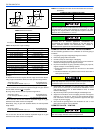
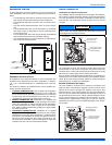
IGNITION SYSTEM SEQUENCE
1. Turn the gas supply ON at external valve and main gas valve.
2. Set the thermostat above room temperature to call for heat.
3. System start-up will occur as follows:
a. The induced draft blower motor will start and come up to speed.
Shortly after inducer start-up, the hot surface igniter will glow for
about 17 seconds.
b. After this warm up, the ignition module will energize (open) the
main gas valve.
c. After flame is established, the supply air blower will start in about
30 seconds.
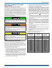
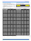
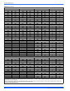
CALCULATING THE FURNACE INPUT (NAT. GAS)
Burner orifices are sized to provide proper input rate using natural gas
with a heating value of 1030 BTU/Ft
3
(38.4 MJ/m
3
). If the heating value
of your gas is significantly different, it may be necessary to replace the
orifices.
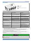
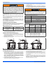
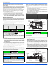
FIGURE 39: Attic and Crawl Space Combustion Air Termination
Be sure to instruct the owner not to block this intake pipe.
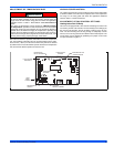
All electrical connections made in the field and in the factory should
be checked for proper tightness.
FIRE OR EXPLOSION HAZARD
Failure to follow the safety warnings exactly could result in serious
injury, death or property damage.
Never test for gas leaks with an open flame. Use a commercially
available soap solution made specifically for the detection of leaks to
check all connections. A fire or explosion may result causing property
damage, personal injury or loss of life.
Burner ignition may not be satisfactory on first startup due to residual
air in the gas line or until gas manifold pressure is adjusted. The igni-
tion control will make three attempts to light before locking out.
12” Min.
12” minimum
between bottom
of air intake and
any material below.
HOT SURFACE IGNITION SYSTEM
Do not attempt to light this furnace by hand (with a match or any
other means). There may be a potential shock hazard from the
components of the hot surface ignition system. The furnace can
only be lit automatically by its hot surface ignition system.
DO NOT set manifold pressure less than 3.2” w.c. or more than 3.8”
w.c. for natural gas at sea level. If manifold pressure is outside this
range, change main burner orifices.
If orifice hole appears damaged or it is suspected to have been
redrilled, check orifice hole with a numbered drill bit of correct size.
Never redrill an orifice. A burr-free and squarely aligned orifice hole is
essential for proper flame characteristics.
DO NOT bottom out gas valve regulator adjusting screw. This can
result in unregulated manifold pressure and result in excess overfire
and heat exchanger failures.
NOTICE
NOTICE