


701379-UIM-C-0712
12 Johnson Controls Unitary Products
SECTION V: ELECTRICAL POWER
ELECTRICAL POWER CONNECTIONS
Field wiring to the unit must be grounded. Electric wires that are field
installed shall conform to the temperature limitation for 63°F (35°C) rise
wire when installed in accordance with instructions. Refer to Table 7 in
these instructions for specific furnace electrical data.
Annual Fuel Utilization Efficiency (AFUE) numbers are determined in accordance with DOE test procedures.
Wire size and over current protection must comply with the National Electrical Code (NFPA-70-latest edition) and all local codes.
The furnace shall be installed so that the electrical components are protected from water.
SUPPLY VOLTAGE CONNECTIONS
1. Provide a power supply separate from all other circuits. Install over-
current protection and disconnect switch per local/national electrical
codes. The switch should be close to the unit for convenience in
servicing. With the disconnect or fused switch in the OFF position,
check all wiring against the unit wiring label. Refer to the wiring dia-
gram in this instruction.
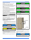
2. Remove the wiring box cover screws. Route all power wiring
through a conduit connector or other proper bushing that has been
installed into the unit opening and the junction box. In the junction
box there is a black wire, a white wire and a green ground screw.
Connect the power supply as shown on the unit’s wiring label
located on the inside of the blower compartment door, or the wiring
schematic in this section. Connect the black wire to L1 (hot) from
the power supply. Connect the white wire to neutral. Connect the
ground wire (installer-supplied) to the green (equipment ground)
screw. An alternate wiring method is to use a field-provided 2”
(5.1 cm) x 4” (10.2 cm) box and cover on the outside of the furnace.
Route the furnace leads into the box using a protective bushing
where the wires pass through the furnace panel. After making the
wiring connections replace the wiring box cover and screws. Refer
to Figure 17.
3. The furnace's control system requires correct polarity of the power
supply and a proper ground connection. Refer to Figure 17.
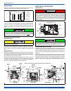
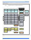
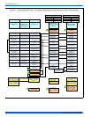
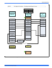
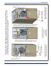
LOW VOLTAGE CONTROL WIRING CONNECTIONS
Install the field-supplied thermostat by following the instructions that
come with the thermostat. With the thermostat set in the OFF position
and the main electrical source disconnected, connect the thermostat
wiring from the wiring connections on the thermostat to the terminal
board on the ignition module, as shown in Figures 18 - 21. Electronic
thermostats may require the common wire to be connected. Apply
strain relief to thermostat wires passing through cabinet. If air condition-
ing equipment is installed, use thermostat wiring to connect the Y and C
terminals on the furnace control board to the proper wires on the con-
densing unit (unit outside).
The 24-volt, 40 VA transformer is sized for the furnace components
only, and should not be connected to power auxiliary devices such as
humidifiers, air cleaners, etc. The transformer may provide power for an
air conditioning unit contactor.
Use copper conductors only.
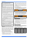
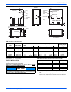
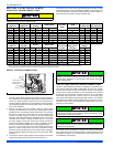
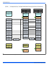
Table 7: Ratings & Physical / Electrical Data
Input
High/Low
Output
High/Low
Nominal
Airflow
Cabinet Width
Total Unit
Amps
AFUE
High Fire
Air Temp. Rise
Low Fire
Air Temp. Rise
MBH kW MBH kW CFM
m
3
/min
in. cm % °F °C °F °C
40/26 12/8 38/25 11/7 1000 28.3 14-1/2 36.8 9 96 30 - 60 17-33 20-50 11-28
60/39 18/11 58/37 17/11 1200 34 17-1/2 44.4 9 96 35 - 65 19-36 35-65 19-36
80/52 23/15 77/50 22/14 1200 34 17-1/2 44.4 9 96 40 - 70 22-39 35-65 19-36
80/52 23/15 77/50 22/14 1600 45.3 21 53.3 12 96 35 - 65 19-36 35-65 19-36
100/65 29/19 96/62 28/18 1600 45.3 21 53.3 12 96 35 - 65 19-36 30-60 17-33
100/65 29/19 96/62 28/18 2000 56.6 21 53.3 14 96 35 - 65 19-36 35-65 19-36
120/78 35/23 115/75 33/22 2000 56.6 24-1/2 62.2 14 96 35 - 65 19-36 35-65 19-36
Input
High/Low
Max. Outlet
Air Temp.
Blower Blower Size
Max.
Over-current
Protect
Min. Wire Size
(awg) @ 75 ft.
One Way
Operating
Weight
MBH kW °F °C HP Amps in. cm Lbs. Kg.
40/26 12/8 180 82.2 1/2 7 11 x 8 27.9 x 20.3 15 14 113 51.2
60/39 18/11 170 76.7 1/2 7 11 x 8 27.9 x 20.3 15 14 122 55.3
80/52 23/15 175 79.4 1/2 7 11 x 8 27.9 x 20.3 15 14 126 57.1
80/52 23/15 175 79.4 3/4 10.2 11 x 10 27.9 x 25.4 15 14 136 61.7
100/65 23/15 175 79.4 3/4 10.2 11 x 10 27.9 x 25.4 15 14 142 64.4
100/65 29/19 175 79.4 1 12.7 11 x 11 27.9 x 27.9 20 12 145 65.7
120/78 35/23 170 76.7 1 12.7 11 x 11 27.9 x 27.9 20 12 156 70.7
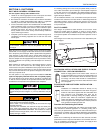
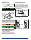
FIGURE 17: Electrical Wiring
Electrical Entry
Junction
Box
L1-Hot
Neutral
Connect ground
lead to screw
BLK
WHT
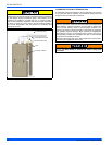
The power connection leads and wiring box may be relocated to the
left side of the furnace. Remove the screws and cut wire tie holding
excess wiring. Reposition on the left side of the furnace and fasten
using holes provided.
Set the heat anticipator in the room thermostat to 0.4 amps. Setting it
lower will cause short cycles. Setting it higher will cause the room
temperature to exceed the set points.
Some electronic thermostats do not have adjustable heat anticipa-
tors. They should be set to six cycles per hour. Follow the thermostat
manufacturer's instructions.