


701379-UIM-C-0712
Johnson Controls Unitary Products 35
SECTION IX: SAFETY CONTROLS
CONTROL CIRCUIT FUSE
A 3-amp fuse is provided on the control circuit board to protect the 24-
volt transformer from overload caused by control circuit wiring errors.
This is an ATO 3, automotive type fuse and is located on the control
board.
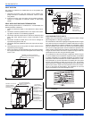
BLOWER DOOR SAFETY SWITCH
This unit is equipped with an electrical interlock switch mounted in the
burner compartment. This switch interrupts all power at the unit when
the panel covering the blower compartment is removed.
Electrical supply to this unit is dependent upon the panel that covers the
blower compartment being in place and properly positioned.
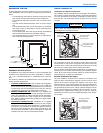
ROLLOUT SWITCH CONTROLS
These controls are mounted on the burner assembly. If the temperature
in the area surrounding burner exceeds its set point, the gas valve is
de-energized. The operation of this control indicates a malfunction in
the combustion air blower, heat exchanger or a blocked vent pipe con-
nection. Corrective action is required. These are manual reset controls
that must be reset before operation can continue.
PRESSURE SWITCHES
This furnace is supplied with three pressure switches, which monitor the
flow through the combustion air/vent piping and condensate drain sys-
tem. These switches de-energize the gas valve if any of the following
conditions are present. Refer to SECTION VI, "CONDENSATE PIPING
AND FURNACE VENTING CONFIGURATION" for tubing connections.
1. Blockage of vent piping or terminal.
2. Failure of combustion air blower motor.
3. Blockage of combustion air piping or terminals.
4. Blockage of condensate drain piping.
LIMIT CONTROLS
There is a high temperature limit control located on the furnace vesti-
bule panel near the gas valve. This is an automatic reset control that
provides over temperature protection due to reduced airflow. This may
be caused by:
1. A dirty filter.
2. If the indoor fan motor should fail.
3. Too many supply or return registers closed or blocked off.
The control module will lockout if the limit trips 5 consecutive times.
If this occurs, control will reset & try ignition again after 1 hour.
SECTION X: NORMAL OPERATION AND
DIAGNOSTICS
NORMAL OPERATION SEQUENCE
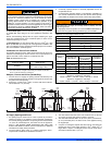
Heating and Cooling Airflow
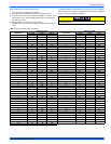
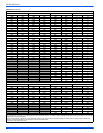
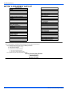
The heating and the cooling airflows are preset at the factory. The heat-
ing airflow is set to the maximum CFM. The cooling airflow is set to pro-
vide 90 percent of the maximum CFM. The heating and cooling airflows
must be field adjusted to match the HVAC system at installation. See
Table 18 for the HEAT, COOL and ADJ jumper settings to use for spe-
cific airflows.
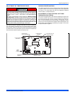
CFM Board - Delay Taps Selection
The set of jumper pins on the control board labeled DELAY are used to
set the delay profiles for the furnace. These can be chosen so as to
maximize the comfort and sound levels for various regions of the coun-
try.
Tap A is the default profile. It provides a 30-second ramp-up from zero
airflow to full capacity and a 30-second ramp-down from full capacity
back to zero airflow. Whenever there is a change in airflow mode, such
as from low heat to high heat, the motor will take 30 seconds to ramp
from one speed to the other.
Tap B is the humid profile. This profile is best-suited for installations
where the humidity is frequently very high during cooling season, such
as in the southern part of the country. On a call for cooling, the blower
will ramp up to 50% of full capacity and will stay there for two minutes,
then will ramp up to 82% of full capacity and will stay there for five min-
utes, and then will ramp up to full capacity, where it will stay until the
wall thermostat is satisfied. In every case, it will take the motor 30 sec-
onds to ramp from one speed to another.
Tap C is the dry profile. This profile is best suited to parts of the country
where excessive humidity is not generally a problem, where the sum-
mer months are usually dry. On a call for cooling the motor will ramp up
to full capacity and will stay there until the thermostat is satisfied. At the
end of the cooling cycle, the blower will ramp down to 50% of full capac-
ity where it will stay for 60 seconds. Then it will ramp down to zero. In
every case, it will take the motor 30 seconds to ramp from one speed to
another.
Tap D is the normal profile, best suited for most of the country, where
neither excessive humidity nor extremely dry conditions are the norm.
On a call for cooling, the motor will ramp up to 63% of full capacity and
will stay there for 90 seconds, then will ramp up to full capacity. At the
end of the cooling cycle, the motor will ramp down to 63% of full capac-
ity and will stay there for 30 seconds, then will ramp down to zero. In
every case, it will take the motor 30 seconds to ramp from one speed to
another.
Continuous Blower Operation
The blower will run continuously whenever the wall thermostat fan
switch is in the ON position. The furnace blower will run at the speed
selected on the FAN SPEED jumpers on the main control board
(HI COOL, LO COOL, HI HEAT or LO HEAT). When the jumper is in the
VS G position, the blower will run at 50% of the high cool speed.
Intermittent Blower Cooling
On cooling/ heating thermostats with a fan switch, when the fan switch
is set in the auto position and the thermostat calls for cooling, a circuit is
completed between the R, Y and G terminals. The motor is energized
through the Y1 cool terminal and runs on the speed selected on the
COOL tap of the control board. The fan off setting is fixed at 60 seconds
for SEER enhancement. The control board can accommodate two-
stage cooling. When a two-stage cool thermostat is connected to the Y1
and Y2 terminals on the board, the blower will operate on LOW COOL
speed when Y1 is energized and on HI COOL speed when Y1 and Y2
are energized.
Intermittent Blower Heating
On cooling/ heating thermostats with a fan switch, when the fan switch
is set in the auto position and the thermostat calls for heating, a circuit is
completed between the R and W terminals. The indoor fan motor is
energized through the W1 heat terminal and runs on the speed selected
on the HEAT tap of the control board.
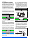
Humidistat
When a humidistat is installed in the system, the “Humidistat Installed?”
jumper on the control board should be moved to the YES position.
The cooling CFM will then be reduced by 15% whenever the humidistat
indicates high humidity.
Main power to the unit must still be interrupted at the main power dis-
connect switch before any service or repair work is to be done to the
unit. Do not rely upon the interlock switch as a main power discon-
nect.
Blower and burner must never be operated without the blower panel
in place.