


701379-UIM-C-0712
Johnson Controls Unitary Products 29
6. An air inlet supply from outdoors shall be equipped with a means to
prevent the direct entry of rain and wind. Such means shall not
reduce the required free area of the air supply opening.
7. An air supply inlet opening from the outdoors shall be located not
less than 12” (30.5 cm) above the outside grade level.
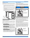
Combustion Air Source from Outdoors
1. Two permanent openings, one within 12” (30.5 cm) of the top and
one within 12” (30.5 cm) of bottom of the confined space, Two per-
manent openings, shall communicate directly or by means of ducts
with the outdoors, crawl spaces or attic spaces.
2. One permanent openings, commencing within 12” (30.5 cm) of the
top of the enclosure shall be permitted where the equipment has
clearances of at least 1” (2.54 cm) from the sides and back and 6”
(15.2 cm) from the front of the appliance. The opening shall com-
municate directly with the outdoors and shall have a minimum free
area of:
a. 1 square in. per 3000 Btu per hour (6.45 cm
3
per 0.879 kW) of
the total input rating of all equipment located in the enclosure.
b. Not less than the sum of all vent connectors in the confined
space.
3. The duct shall be least the same cross-sectional area as the free
area of the air supply inlet opening to which it connects.
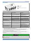
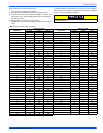
4. The blocking effects of louvers, grilles and screens must be given
consideration in calculating free area. If the free area of a specific
louver or grille is not known. Refer to Table 12.
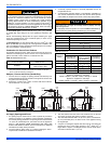
Ventilated Combustion Air
The ventilated attic space or a crawl space from which the combustion
air is taken must comply with the requirements specified in “AIR
SOURCE FROM OUTDOORS” in this instruction or in Section 5.3, Air
for Combustion and Ventilation of the National Fuel Gas Code, ANSI
Z223.1 (latest edition). This type installation requires two properly sized
pipes. One brings combustion air from a properly ventilated attic space
or crawl space and a second pipe that extends from the furnace vent
connection (top right of unit) to the exterior of the building. Refer to
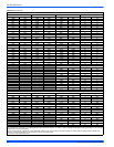
Table 8 for intake pipe sizing, allowable length and elbow usage. Follow
all notes, procedures and required materials in the "COMBUSTION
AIR/VENT PIPE SIZING" section in these instructions when installing
the combustion air pipe from the unit and into a ventilated attic space or
crawl space. DO NOT terminate vent pipe in an Attic or Crawl Space.
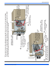
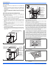
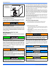
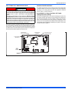
Ventilated Combustion Air Termination
Refer to Figure 38 for required attic termination for the combustion air
intake pipe. For attic termination, use two 90° elbows with the open end
in a downward position. Be sure to maintain 12” (30.5 cm) clearance
above any insulation, flooring or other material.
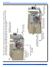
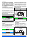
A crawl space combustion air installation consists of a straight pipe from
the PVC coupling on the burner box that extends into the crawl space
and terminates with a 1/4” (6.4 mm) mesh screen and no elbows.
CARBON MONOXIDE POISONING HAZARD
Failure to follow the steps outlined below for each appliance connected to the venting system being placed into operation could result in carbon-
monxide poisoning or death.
The following steps shall be followed for each appliance connected to the venting system being placed into operation, while all other appliances
connected to the venting system are not in operation:
1. Inspect the venting system for proper size and horizontal pitch. Determine that there is no blockage, restriction, leakage, corrosion or other defi-
ciencies, which could cause an unsafe condition
2. Close all building doors and windows and all doors.
3. Turn on clothes dryers and TURN ON any exhaust fans, such as range hoods and bathroom exhausts, so they shall operate at maximum
speed. Open the fireplace dampers. Do not operate a summer exhaust fan.
4. Follow the lighting instructions. Place the appliance being inspected in operation. Adjust thermostat so the appliance shall operate continu-
ously.
5. Test each appliance (such as a water heater) equipped with a draft hood for spillage (down-draft or no draft) at the draft hood relief opening
after 5 minutes of main burner operation. Appliances that do not have draft hoods need to be checked at the vent pipe as close to the appliance
as possible. Use a combustion analyzer to check the CO
2
and CO levels of each appliance. Use a draft gauge to check for a downdraft or inad-
equate draft condition.
6. After it has been determined that each appliance properly vents when tested as outlined above, return doors, windows, exhaust fans, fireplace
dampers and any other gas burning appliance to their normal condition.
7. If improper venting is observed during any of the above tests, a problem exists with either the venting system or the appliance does not have
enough combustion air (Supply Air from outside) to complete combustion. This condition must be corrected before the appliance can function
safely.
NOTE: A unsafe condition exists when the CO reading exceeds 40 ppm and the draft reading is not in excess of - 0.1 in. w.c. (-25 kPa) with all
of the appliance(s) operating at the same time.
8. Any corrections to the venting system and / or to the supply (outside) air system must be in accordance with the National Fuel Gas Code
Z223.1 or CAN/CGA B149.1 Natural Gas and Propane Installation Code (latest editions). If the vent system must be resized, follow the appro-
priate tables in Appendix G of the above codes or for this appliance.