


701379-UIM-C-0712
28 Johnson Controls Unitary Products
An unconfined space is not less than 50 cu.ft (1.42 m
3
) per 1,000 Btu/
hr (0.2928 kW) input rating for all of the appliances installed in that
area.
Rooms communicating directly with the space containing the appli-
ances are considered part of the unconfined space, if doors are fur-
nished with openings or louvers.
A confined space is an area with less than 50 cu.ft (1.42 m
3
) per 1,000
Btu/hr (0.2928 kW) input rating for all of the appliances installed in that
area. The following must be considered to obtain proper air for combus-
tion and ventilation in confined spaces.
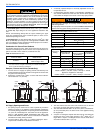
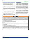
Combustion Air Source From Outdoors
The blocking effects of louvers, grilles and screens must be given con-
sideration in calculating free area. If the free area of a specific louver or
grille is not known, refer to Table 12, to estimate free area.
* Do not use less than 1/4” (6.4 mm) mesh
+ Free area of louvers and grille varies widely; the installer should follow
louver or grille manufacturer’s instructions.
Dampers, Louvers and Grilles (Canada Only)
1. The free area of a supply air opening shall be calculated by sub-
tracting the blockage area of all fixed louvers grilles or screens from
the gross area of the opening.
2. Apertures in a fixed louver, a grille, or screen shall have no dimen-
sion smaller than 1/4” (6.4 mm).
3. A manually operated damper or manually adjustable louvers are
not permitted for use.
4. A automatically operated damper or automatically adjustable lou-
vers shall be interlocked so that the main burner cannot operate
unless either the damper or the louver is in the fully open position.
Air Supply Openings and Ducts
1. An opening may be used in lieu of a duct to provide to provide the
outside air supply to an appliance unless otherwise permitted by
the authority having jurisdiction. The opening shall be located within
12” (30.5 cm) horizontally from, the burner level of the appliance.
Refer to “AIR SOURCE FROM OUTDOORS AND VENT AND
SUPPLY AIR SAFETY CHECK” in these instructions for additional
information and safety check procedure.
2. The duct shall be either metal, or a material meeting the class 1
requirements of CAN4-S110 Standard for Air Ducts.
3. The duct shall be least the same cross-sectional area as the free
area of the air supply inlet opening to which it connects.
4. The duct shall terminate within 12” (30.5 cm) above, and within 24”
(61 cm) horizontally from, the burner level of the appliance having
the largest input.
5. A square or rectangular shaped duct shall only be used when the
required free area of the supply opening is 9 in
2
(58.06 cm
2
) or
larger. When a square or rectangular duct is used, its small dimen-
sion shall not be less than 3” (7.6 cm).
This type of installation requires that the supply air to the appliance(s)
be of a sufficient amount to support all of the appliance(s) in the area.
Operation of a mechanical exhaust, such as an exhaust fan, kitchen
ventilation system, clothes dryer or fireplace may create conditions
requiring special attention to avoid unsatisfactory operation of gas
appliances. A venting problem or a lack of supply air will result in a
hazardous condition, which can cause the appliance to soot and gen-
erate dangerous levels of CARBON MONOXIDE, which can lead to
serious injury, property damage and / or death.
Table 12: Estimated Free Area
Wood or Metal
Louvers or Grilles
Wood 20-25%*
Metal 60-70% *
Screens+
1/4” (6.4 mm)
mesh or larger 100%
When a Category I furnace is removed or replaced, the original vent-
ing system may no longer be correctly sized to properly vent the
attached appliances.
An improperly sized vent system can cause CARBON MONOXIDE to
spill into the living space causing personal injury, and or death.
Table 13: Unconfined Space Minimum Area
BTUH Input Rating Minimum Free Area Required for Each Opening
40,000
40 in
2
(258 cm
2
)
60,000
60 in
2
(387 cm
2
)
80,000
80 in
2
(516 cm
2
)
100,000
100 in
2
(645 cm
2
)
120,000
120 in
2
(742 cm
2
)
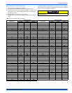
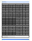
Table 14: Free Area
BTUH Input
Rating
Minimum Free Area Required for Each Opening
Horizontal Duct
(2,000 BTUH)
Vertical Duct or
Opening to Outside
(4,000 BTUH)
Round Duct
(4,000 BTUH)
40,000
20 in
2
(129 cm
2
)10 in
2
(64 cm
2
)
4” (10 cm)
60,000
30 in
2
(193 cm
2
)15 in
2
(97 cm
2
)
5” (13 cm)
80,000
40 in
2
(258 cm
2
) 20 in
2
(129 cm
2
)
5” (13 cm)
100,000
50 in
2
(322 cm
2
) 25 in
2
(161 cm
2
)
6” (15 cm)
120,000
60 in
2
(387 cm
2
) 30 in
2
(193 cm
2
)
7” (18 cm)
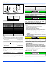
EXAMPLE: Determining Free Area.
Appliance 1 Appliance 2 Total Input
100,000 +30,000 = (130,000 4,000) = 32.5 Sq. In. Vertical
Appliance 1 Appliance 2 Total Input
100,000 +30,000 = (130,000 2,000) = 65 Sq. In. Horizontal
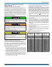
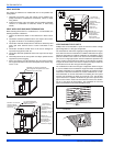
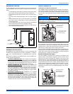
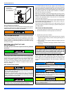
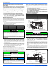
FIGURE 38: Outside and Ambient Combustion Air
Gable
Vent
Gas
Vent
Soffit
Vent
Ventilated
Attic
TopAbove
Insulation
Optional
Inlet (a)
Outlet
Air (a)
Ventilated
Crawl Space
Gas
Water
Heater
Furnace
Soffit
Vent
Gas
Water
Heater
Inlet
Air (a)
Inlet
Air (b)
Furnace
Gas
Vent
Outlet
Air (a)
Outlet
Air (b)
Inlet
Air (a)
Inlet
Air (b)
Gas
Water
Heater
Furnace
Gable
Vent
Gas
Vent
Ventilated
Attic
TopAbove
Insulation