


701379-UIM-C-0712
36 Johnson Controls Unitary Products
Heating Cycle
When the thermostat switch is set on HEAT and the fan is set on AUTO,
and there is a call for heat, a circuit is completed between terminals R
and W of the thermostat. When the proper amount of combustion air is
being provided, the pressure switch will close, the ignition control pro-
vides a 17-second ignitor warm-up period, the gas valve then opens,
the gas starts to flow, ignition occurs and the flame sensor begins its
sensing function. The blower motor will energize 30 seconds after the
gas valve opens, if a flame is detected. Normal furnace operation will
continue until the thermostat circuit between R and W is opened, which
causes the ignition system and gas valve to de-energize and the burner
flames to be extinguished. The vent motor will operate for 15 seconds
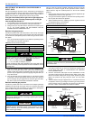
and the blower motor will operate for the amount of time set by the fan-
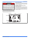
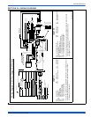
off delay jumper located on the control board. See Figure 41. The heat-
ing cycle is now complete, and ready for the start of the next heating
cycle.
If the flame is not detected within 7 seconds of the gas valve opening,
the gas valve is shut off and a retry operation begins. Also, if the flame
is lost for 2 seconds during the 10-second stabilization period, the gas
valve is shut off and a retry operation begins. During a retry operation,
the vent motor starts a 15 second inter-purge and the ignitor warm-up
time is extended to 27 seconds. If the flame is established for more than
10 seconds after ignition during a retry, the control will clear the ignition
attempt (retry) counter. If three retries occur during a call for heat, the
furnace will shut down for one hour. If at the end of the one hour shut
down there is a call for heat, the furnace will initiate a normal start cycle.
If the problem has not been corrected the furnace will again lockout
after three retries.
A momentary loss of gas supply, flame blowout, or a faulty flame probe
circuit will result in a disruption in the flame and be sensed within 1.0
seconds. The gas valve will de-energize and the control will begin a
recycle operation. A normal ignition sequence will begin after a 15 sec-
ond inter-purge. If during the five recycles the gas supply does not
return, or the fault condition is not corrected the ignition control will lock-
out for 60 minutes.
During burner operation, a momentary loss of power for 50 milliseconds
or longer will de-energize the gas valve. When the power is restored,
the gas valve will remain de-energized and the ignition sequence will
immediately restart.
TROUBLESHOOTING
The following visual checks should be made before troubleshooting:
1. Check to see that the power to the furnace and the ignition control
module is ON.
2. The manual shut-off valves in the gas line to the furnace must be
open.
3. Make sure all wiring connections are secure.
4. Review the sequence of operation. Start the system by setting the
thermostat above the room temperature. Observe the system’s
response. Then use the troubleshooting section in this manual to
check the system’s operation.
FURNACE CONTROL DIAGNOSTICS
The furnace has built-in, self-diagnostic capability. A blinking LED light
on the control board can flash red, green or amber to indicate various
conditions. The control continuously monitors its own operation and the
operation of the system. If a failure occurs, the LED light will indicate
the failure code.
The SLOW flash speed is two seconds on and two seconds off.
The other flash codes listed below have the following timing: LED light
will turn on for 1/3 second and off for 1/3 second. This pattern will be
repeated the number of times equal to the code. There will be a two-
second pause between codes. For example, the six red flash code will
flash the LED light on and off six times, then will be off for two seconds.
This pattern will repeat as long as the fault condition remains. The con-
tinuous flash codes listed below will flash the LED light on and off con-
tinuously, with no breaks or longer pauses.
SLOW GREEN FLASH: Normal operation, no thermostat calls.
SLOW AMBER FLASH: Normal operation with call for heat.
LED STEADY OFF – If the LED light does not flash at all, check for
power to the board and check for a blown fuse on the board. If the
board is properly powered and the fuse is not blown, the control board
may need to be replaced.
STEADY ON ANY COLOR: Control failure. Turn power to the furnace
off and back on. If the fault code returns, the control board must be
replaced. The control board is not field-repairable.
CONTINUOUS AMBER FLASH: Flame sense current is below 1.5
microamps. Check and clean flame sensor. Check for proper gas flow.
Verify that current is greater than 1.5 microamps at flame current test
pad.
1 RED FLASH: This indicates that flame was sensed when there was
not a call for heat. The control will turn on both the inducer motor and
supply air blower. Check for a leaking or slow-closing gas valve.
2 RED FLASHES: This indicates that the pressure switch is closed
when it should be open. The control confirms that the pressure switch
contacts are open at the beginning of each heat cycle and will not let
the ignition sequence continue if the pressure switch contacts are
closed when they should be open. Check for a faulty pressure switch or
miswiring.
3 RED FLASHES: This indicates the pressure switch contacts are open
when they should be closed. Check for faulty inducer, blocked vent
pipe, broken pressure switch hose, disconnected pressure switch or
inducer wires or faulty pressure switch.
4 RED FLASHES: This indicates that the main limit switch has opened
its normally closed contacts. The control will turn on the supply air
blower and inducer. Check for a dirty filter, improperly sized duct sys-
tem, incorrect blower speed setting, incorrect firing rate, loose limit
switch wiring or faulty blower motor.
If the limit switch has not closed within five minutes, the control will
assume that the blower is not functioning, will start a hard lockout and
will begin to flash the 11 Red Flashes error code. If, after fifteen min-
utes, the main limit still has not closed, the control will assume that a
manual-reset rollout switch has opened and will begin to flash the 5 Red
Flash error code. See the description of “5 Red Flashes” and “11Red
Flashes” below.
If the main limit switch opens five times within a single call for heat, the
control will indicate 4 Red Flashes and will enter a one-hour soft lock-
out.
Never bypass any safety control to allow furnace operation. To
do so will allow furnace to operate under potentially hazardous
conditions.
Do not try to repair controls. Replace defective controls with
UPG Source 1 Parts.
Never adjust pressure switch to allow furnace operation.