


701379-UIM-C-0712
RESIDENTIAL GAS FURNACE
MODELS: TM9V*MP
(96% AFUE Two Stage
Variable Speed ECM Multi-position)
INSTALLATION MANUAL
LIST OF SECTIONS
SAFETY . . . . . . . . . . . . . . . . . . . . . . . . . . . . . . . . . . . . . . . . . . . 2
DUCTWORK . . . . . . . . . . . . . . . . . . . . . . . . . . . . . . . . . . . . . . . . 5
FILTERS . . . . . . . . . . . . . . . . . . . . . . . . . . . . . . . . . . . . . . . . . . . 9
GAS PIPING . . . . . . . . . . . . . . . . . . . . . . . . . . . . . . . . . . . . . . . 10
ELECTRICAL POWER . . . . . . . . . . . . . . . . . . . . . . . . . . . . . . . 12
CONDENSATE PIPING AND FURNACE
VENTING CONFIGURATION . . . . . . . . . . . . . . . . . . . . . . . . . . 17
COMBUSTION AIR and VENT SYSTEM . . . . . . . . . . . . . . . . . 23
START-UP AND ADJUSTMENTS . . . . . . . . . . . . . . . . . . . . . . 30
SAFETY CONTROLS . . . . . . . . . . . . . . . . . . . . . . . . . . . . . . . . 35
NORMAL OPERATION AND DIAGNOSTICS . . . . . . . . . . . . . 35
REPLACEMENT PARTS LIST . . . . . . . . . . . . . . . . . . . . . . . . . 38
REPLACEMENT PART CONTACT INFORMATION . . . . . . . . 38
WIRING DIAGRAM . . . . . . . . . . . . . . . . . . . . . . . . . . . . . . . . . . 39
LIST OF FIGURES
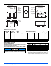
Duct Attachment . . . . . . . . . . . . . . . . . . . . . . . . . . . . . . . . . . . . . . . . . 5
Vertical Applications . . . . . . . . . . . . . . . . . . . . . . . . . . . . . . . . . . . . . . 6
Coil Flange . . . . . . . . . . . . . . . . . . . . . . . . . . . . . . . . . . . . . . . . . . . . . 6
Horizontal Right Application . . . . . . . . . . . . . . . . . . . . . . . . . . . . . . . . 6
Horizontal Left Application . . . . . . . . . . . . . . . . . . . . . . . . . . . . . . . . . 6
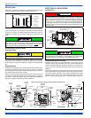
PC Series Upflow Coil Installation . . . . . . . . . . . . . . . . . . . . . . . . . . . 7
Horizontal Left or Right application (Right Shown) . . . . . . . . . . . . . . 7
Combustible Floor Base Accessory . . . . . . . . . . . . . . . . . . . . . . . . . . 7
Horizontal Application . . . . . . . . . . . . . . . . . . . . . . . . . . . . . . . . . . . . 8
Typical Attic Installation . . . . . . . . . . . . . . . . . . . . . . . . . . . . . . . . . . . 8
Typical Suspended Furnace / Crawl Space Installation . . . . . . . . . . . 8
Downflow Venting . . . . . . . . . . . . . . . . . . . . . . . . . . . . . . . . . . . . . . . 8
Dimensions . . . . . . . . . . . . . . . . . . . . . . . . . . . . . . . . . . . . . . . . . . . . 9
Side Return Cutout Markings . . . . . . . . . . . . . . . . . . . . . . . . . . . . . . 10
Gas Valve . . . . . . . . . . . . . . . . . . . . . . . . . . . . . . . . . . . . . . . . . . . . . 10
Gas Piping . . . . . . . . . . . . . . . . . . . . . . . . . . . . . . . . . . . . . . . . . . . . 10
Electrical Wiring . . . . . . . . . . . . . . . . . . . . . . . . . . . . . . . . . . . . . . . . 12
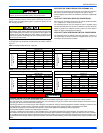
Thermostat Chart - Single Stage Air Conditioners
with Two Stage Variable Speed Furnaces . . . . . . . . . . . . . . . . . . . . 13
Thermostat Chart - Single Stage Heat Pump with Two Stage
Variable Speed Furnace (Hot Heat Pump or Conventional) . . . . . . 14
Thermostat Chart - Two Stage AC with
Two Stage Variable Speed Furnace . . . . . . . . . . . . . . . . . . . . . . . . 15
Thermostat Chart - Two Stage HP with Two Stage
Variable Speed Furnace (Hot Heat Pump or Conventional) . . . . . . .16
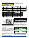
Typical. Condensate drain, vertical installation . . . . . . . . . . . . . . . . .17
Typical. Combustion Pipe Drain Tee . . . . . . . . . . . . . . . . . . . . . . . .18
Upflow Configuration . . . . . . . . . . . . . . . . . . . . . . . . . . . . . . . . . . . .19
Downflow Configuration . . . . . . . . . . . . . . . . . . . . . . . . . . . . . . . . . .20
Horizontal Left Configuration . . . . . . . . . . . . . . . . . . . . . . . . . . . . . .21
Horizontal Right Configuration . . . . . . . . . . . . . . . . . . . . . . . . . . . . .22
Dimensions . . . . . . . . . . . . . . . . . . . . . . . . . . . . . . . . . . . . . . . . . . . .24
Home Layout . . . . . . . . . . . . . . . . . . . . . . . . . . . . . . . . . . . . . . . . . .25
Termination Configuration - 1 Pipe . . . . . . . . . . . . . . . . . . . . . . . . . .26
Termination Configuration - 2 Pipe . . . . . . . . . . . . . . . . . . . . . . . . . .26
Termination Configuration - 2 Pipe Basement . . . . . . . . . . . . . . . . .26
Double Horizontal Combustion Air Intake and Vent Termination . . .26
Double Vertical Combustion Air Intake and Vent Termination . . . . .26
Downward Venting . . . . . . . . . . . . . . . . . . . . . . . . . . . . . . . . . . . . . .27
Direct Vent Air Intake Connection and Vent Connection . . . . . . . . .27
Combustion Airflow Path Through The Furnace Casing . . . . . . . . .27
Outside and Ambient Combustion Air . . . . . . . . . . . . . . . . . . . . . . . .28
Attic and Crawl Space Combustion Air Termination . . . . . . . . . . . . .30
Gas Valve . . . . . . . . . . . . . . . . . . . . . . . . . . . . . . . . . . . . . . . . . . . . .32
Reading Gas Pressure 3 . . . . . . . . . . . . . . . . . . . . . . . . . . . . . . . . . . .2
Furnace Control Board . . . . . . . . . . . . . . . . . . . . . . . . . . . . . . . . . . 33
Wiring Diagram . . . . . . . . . . . . . . . . . . . . . . . . . . . . . . . . . . . . . . . . .39
LIST OF TABLES
Unit Clearances to Combustibles . . . . . . . . . . . . . . . . . . . . . . . . 4
Coil Projection Dimensions - PC Series Coils . . . . . . . . . . . . . . . 7
Cabinet and Duct Dimensions . . . . . . . . . . . . . . . . . . . . . . . . . . . 9
Recommended Filter Sizes (High Velocity 600 FPM) . . . . . . . . . 9
Nominal Manifold Pressure - High Fire . . . . . . . . . . . . . . . . . . . 11
Nominal Manifold Pressure - Low Fire . . . . . . . . . . . . . . . . . . . 11
Ratings & Physical / Electrical Data . . . . . . . . . . . . . . . . . . . . . 12
Maximum Equivalent Pipe Length . . . . . . . . . . . . . . . . . . . . . . . 23
Elbow Dimensions . . . . . . . . . . . . . . . . . . . . . . . . . . . . . . . . . . . 24
Equivalent Length of Fittings . . . . . . . . . . . . . . . . . . . . . . . . . . . 24
Combustion Air Intake and Vent Connection
Size at Furnace (All Models) . . . . . . . . . . . . . . . . . . . . . . . . . . . 24
Estimated Free Area . . . . . . . . . . . . . . . . . . . . . . . . . . . . . . . . . 28
Unconfined Space Minimum Area . . . . . . . . . . . . . . . . . . . . . . . 28
Free Area . . . . . . . . . . . . . . . . . . . . . . . . . . . . . . . . . . . . . . . . . 28
Gas Rate (CU FT/HR) at Full Input . . . . . . . . . . . . . . . . . . . . . . 31
Inlet Gas Pressure Range . . . . . . . . . . . . . . . . . . . . . . . . . . . . . 32
Nominal Manifold Pressure . . . . . . . . . . . . . . . . . . . . . . . . . . . . 32
Air Flow Data . . . . . . . . . . . . . . . . . . . . . . . . . . . . . . . . . . . . . . . 34
These high efficiency, compact units employ induced combustion, reli-
able hot surface ignition and high heat transfer aluminized tubular heat
exchangers. The units are factory shipped for installation in upflow or
horizontal applications and may be converted for downflow applica-
tions.
These furnaces are designed for residential installation in a basement,
closet, alcove, attic, recreation room or garage and are also ideal for
commercial applications. All units are factory assembled, wired and
tested to assure safe dependable and economical installation and oper-
ation.
These units are Category IV listed and may not be common vented with
another gas appliance as allowed by the National Fuel Gas Code.